Choosing A Charger
With battery banks getting larger & larger and battery technology becoming more and more expensive a quality battery charger is not the place you want to skimp on features or quality.
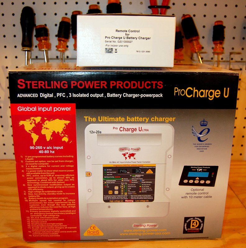
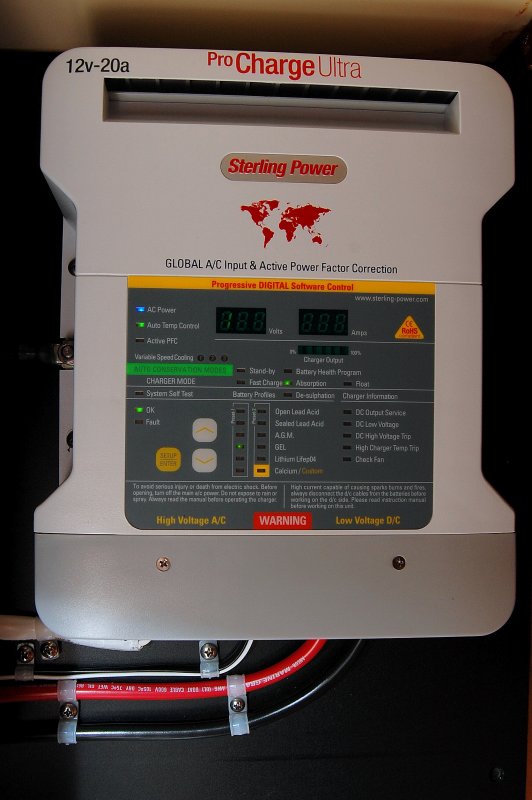
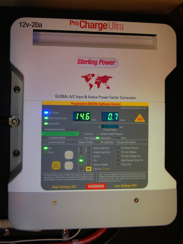
*For this article we are installing a: Sterling ProCharge Ultra Battery Charger
MHT RECOMMENDED CHARGERS:AFILLIATE DISCLAIMER LINK
We recommend buying from Bay Marine Supply. Why? Their pricing is excellent and best of all, they support what they sell! Customer service is important …
BUY STERLING BATTERY CHARGERS – BAY MARINE SUPPLY
BUY STERLING PRODUCTS – AMAZON
*The information in this article, other than specific to the Sterling ProCharge Ultra, can generically apply to all marine battery chargers. Key words here being “marine battery chargers“.
When selecting a marine battery charger, there are certain items that are important to look for:
1- The charger should be built to ABYC / UL 1236 standards. These standards are specific to the marine industry, though I think the emergency market such as rescue and ambulance also use UL 1236. This standard is created around safety and isolation of AC & DC. A UL 1236 charger has undergone a 1500 volt test to ensure there is adequate AC/DC isolation inside the charger. 1500 VOLTS !!!!! While there are some non-marine chargers that can do quite well in the marine environment the UL 1236 or “ABYC” compliant statement or logo will be a good guide and won’t leave you guessing if the charger you chose can handle the environment or is well suited to a marine application.
This quote was published in an ABYC referenced article and written by corrosion survey specialist Stanley Konz.
- Burnt and corroded shore power cords
- Improper AC Neutral to DC negative connections
- Reversed battery cables
- The failure of an automatic inverter ground switch
- Oversized breakers
- A BATTERY CHARGER INPUTTING 110V AC INTO THE BATTERIES!!
- Wire nuts used
- Undersized wire
- Hard (house type) un-tinned wires”
A BATTERY CHARGER INPUTTING 110AC INTO THE BATTERIES……OUCH!
It is critical you choose a well built charger and wire it properly. If you don’t fully understand the above points made by Mr. Konz you should consider consulting a qualified marine electrical systems specialist for this install.
That article goes onto say that nearly 1/3 of the boats in that marina were leaking AC current directly into the water! DIY wiring mistakes, even by those meaning well, can often be a major player in these “leaks”. Please be careful and follow acceptable safety guidelines.
2- The charger should work on varying input voltages and not suffer from output limiting. This Sterling PCU is a “World Voltage” power factor corrected charger and will work on any voltage from 90-260 volts/ 40-80 hz and still supply 100% of its rated output. You can plug this charger in to voltages in just about all countries on the planet. If you’re a cruiser this is a critically important feature. If you have a US voltage charger you’re stuck charging at US voltage/Hz docks.. There are MANY docks out there with voltage drop issues and even at 90 volts AC, with the Sterling PCU, you’re still getting the full rated charger output.
3- The charger should ideally offer physical on-battery temperature sensing, and should ideally come with the sensor as standard equipment, not as an “extra“.
4- The charger should have a good warranty and the manufacturer should have a good reputation for customer service/support. The Sterling charger I am installing for this article happens to carry a 5 year warranty, one of the longest in the industry, and the support from Sterling Power USA has been excellent.
5- The charger should include multiple options for charging voltages/charging profiles plus the ability to create a custom charging profile for batteries not in addressed by a preset list.
6- At a minimum the charger should be multi-stage with at least Bulk, Absorption & Float. I prefer them to also include a Conditioning/Equalizing option.
7- The charger should work well with marine generators. Many chargers, especially non-marine units, do not work well with a marine gen set as the generators do not always output a clean sine wave. The Sterling is PFC so it can handle a wide variety of inputs and tolerates generators that are slightly off spec rather well.
8- For charging wet cell batteries a charger that will revert to an absorption voltage periodically, when left in standby/float mode, is preferred over one that does not. This programmed re-absorption voltage cycle helps to minimize electrolyte stratification. Float voltage alone is not enough to prevent the electrolyte from stratifying. An absorption voltage, run periodically for a short duration, very often prevents the effects of stratification and re-mixes the electrolyte.
NO, NO, NO, NO !!!!!!!!!!!!!!!!!!!!!!!!!!!!!!
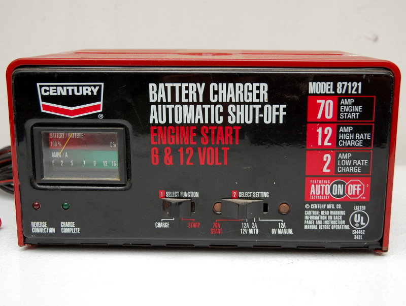 How do I put this politely with regard to using automotive or non-marine UL chargers on boats? Oh yeah, NO !!
Still not understanding why? Okay…….
1- Car chargers, when used on boats, can be one of the worst offenders & cause of stray current corrosion due to their internal architecture which very often does not isolate AC & DC sides like a UL Marine charger will. So this = NO !!
2- Most of the car/auto type battery chargers use what is often referred to as an “autoformer” or autotransfomer. These are transformers with just one winding. Cheap, dirty and they can work ON LAND. Because of this single winding they share a common internally. Portions of the same winding act as both the primary and the secondary. This is bad news and not how a “marine” charger is built. With a marine charger all AC source current runs through the AC hot wire of the charger and is fully returned to shore via the white/neutral wire. The “case” is also grounded to the ships DC ground just in case it becomes energized in an internal fault. Again this = a big NO !!!! DO NOT USE AN AUTOMOTIVE CHARGE ON A BOAT……
3- If the “car charger” has a two prong plug, & many do, especially the older ones we all seem to have lying around the house, these can inadvertently become reversed. This is especially true if your boat has old AC outlets.. Follow me here, if the AC feed neutral & hot are reversed the ships DC negative bus can now become 120V AC with a “car charger”… This is what Mr. Konz observed in my statements in the last photo. You don’t want to be a swimmer near a boat with a cheap car charger on-board, trust me. You also do not want to be the cause of an Electric Shock Drowning or ESD.. So again this = a BIG NO!!!!!!!
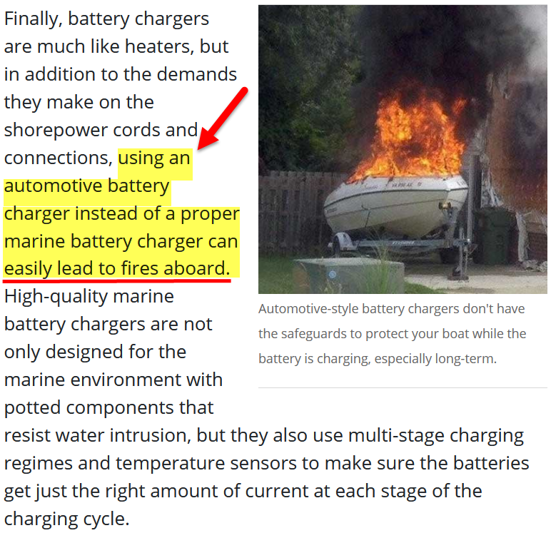
But don’t just take our word for this here is Boat US one of the largest marine insurers in the United States: *Image Courtesy Boat US
How Do I Size A Charger?
This is a decision that is entirely up to the user, with some caveats. The general consensus, & industry recommendation, is to size a hard wired charger for a minimum of 10% of the banks rated Ah capacity, for flooded deep cycle batteries. A 400Ah battery bank, sized at 10%, would get a 40A charger. Sizing at 10% of Ah capacity of course assumes you have the time needed to charge at 10% of Ah capacity and no other loads while charging. Sizing on the larger side, for faster charging, should take into account the battery type you are charging eg: GEL, AGM or Flooded.

Pay Attention to Your Battery Manufacturers Suggested Charging Guidance!
When sizing a charger it is always important to pay attention to minimum charger sizing recommendations. Batteries such as Odyssey TPPL AGM’s, Northstar TPPL AGM’s & Firefly Carbon Foam all benefit from high current charging (40% of installed Ah capacity is advised). Lifeline AGM’s have a minimum recomendation of 20% of installed Ah capacity. This high current charging is beneficial to these batteries and leads to increased cycle-life. Ignoring minimum charging amperage guidance will mean that you’ll not get the optimum cycle life out of the bank.
The image below is for a single Group 31 Odyssey TPPL AGM battery. If you had four of these, for a 400Ah bank, you’d need 160A of charging to meet Odyssey’s “minimum” recommended charger guidance. The ProCharge Ultra can be run in parallel to achieve the minimum charge current guidance for batteries such as these. You can always choose to charge at a lower rate, but you are giving up cycle life by doing so.

The charger can always be larger and this will allow for faster charging.
If you choose to size on the low side, at 10% of Ah capacity, you should also consider any DC loads your boat will use while at the dock. You should always consider the DC dockside loads when trying to get to your minimum 10% sized charger.
For instance some power boats & sailboats have small banks, lets call it a 200Ah bank. A 200Ah house bank would suggest a 20A charger is necessary for a 10% of Ah capacity charge rate. However, what if your on-board loads are consuming 10A? When dockside, DC devices can consume power and rob it from what your charger can feed the bank. On-board items such as DC lighting, DC refrigeration, computers, TV’s stereo etc. are all taking charging potential away from the charger in order to run. Your dockside DC loads reduce the amount of current the charger can supply for battery charging. For example a 10A dock-side load, with a 20A charger, means that 10A is feeding your DC loads and the remaining 10A is going into the bank for charging.
A 20A charger with a 10A dockside load means the battery charger, sized at 10% of bank Ah capacity, is really only supplying 50% of its potential output for charging. This results in a charge rate of just 5% of of the banks Ah capacity. In this case you would need a 30A charger to maintain a charge rate of 10% of Ah capacity. As I said above, “with some caveats“.. Size carefully and don’t forget to consider the dockside DC consumption.
The Sterling Pro Charge Ultra battery chargers have no problem charging a large bank, even pretty small ones, and they can run at full output for many hours, but it does not mean they should. The concern is that all electronics have a shortened life when running hot for long periods of time. Sizing on the small side means a longer bulk charge duration (full charger output) and more heat to dissipate. For the longest duty cycle life a larger charger, that is in bulk for a shorter period, will last the longest. The cooling fan on the Sterling Pro Charge Ultra is a variable output design to let these chargers run quieter. Chargers with single speed fans are most often louder as the fan is either on or off. When sized trending towards larger the fans kick on very rarely but if you go small they work harder and the fan is in use more often.
Some chargers, usually fan-less units or “waterproof” units, can not charge large banks without suffering from damaging internal heat build up. This can result is a drastically shortened life for the charger especially if it is not sized tending towards the larger rather than smaller side. Some chargers reduce or throttle output when they get hot in an attempt to self protect. The more efficient the battery charger is, the less heat it will produce. The Power Factor Corrected Sterling Pro Charge Ultra is near 90% efficient. This is an improvement over non Power Factor Corrected chargers of as much as 40%. Still sizing a charger trending towards the larger side will mean less heat and a longer life.
What the heck does “Power Factor Corrected” mean? What it means is you’ll have a more efficient cooler running charger & less noise/fan run times. It also means a smaller lighter charger with a smaller foot print, because leas heat needs to be dissipated. You’ll also use less AC power to charge at the same DC output than a non Power Factor Corrected charger.
Even the Sterling ProCharge Ultra 60A model will easily run off a Honda EU2000i generator and leave you with plenty of left over wattage, about 700W left over, to run other devices while charging your bank at 60A. NOTE: The Honda EU2000i, a popular gas suitcase generator used on small boats, has a constant load rating of just 1600 watts and is not really a “2000 watt” generator for constant loads.
CAUTION: I DO NOT ENDORSE, CONDONE OR BELIEVE THE USE OF PORTABLE GAS GENERATORS, OF ANY TYPE, ON BOATS, IS SAFE.
I only made the statement above because I recognize there are a fair number of boaters out there who will still do this no matter how much you tell them it is an unwise and unsafe practice. There have been numerous CO poising deaths related to portable generator use on boats.. Be careful and please don’t become a future Darwin Award Winner.
If you had a 400Ah bank, and wanted it charged from 50% state of charge to full, over one day, you could get away with a 20A charger, but I don’t advise it. Of course just because you can charge a 400A bank with a 20A charger does not mean you should, as I have referenced above due to heat.
Conversely if you power your charger off a generator, when away from the dock, as many boaters do, you will want as much charger as your batteries will accept to keep generator run times as short as possible. My one and only real gripe with the Sterling chargers is the largest single charger is 60A. On vessels with large banks or AGM or other types of batteries that have high acceptance rates, a 60A charger can limit your recharge times when using a gen set to charge while away from the dock. For larger chargers Victron & Mastervolt make good ones, or you can simply double up on the Sterling Pro Charge Ultra’s. Using two separate chargers will give you the added benefit of a back up if the other charger fails. In bulk mode, which is what you’d be doing with genset charging, both chargers will be pumping out their maximum current to the bank and you’ll get through bulk pretty quickly. Need more current? You can go to three or more.
Sizing can be a personal preference often based on how quickly you desire to replenish the bank but do keep in mind heat and charger longevity. Deep cycle flooded batteries, such as Rolls, like to be slow charged (10% of Ah capacity), so if your alternator is large, then it may make sense to have a smaller 120V charger for good deep 10% of Ah capacity charges of your thick plate Rolls or industrial type 6V or 2V bank. With boats we often don’t have a choice but to “fast charge” our banks, especially if off cruising.
Adding A Remote Display
More often than not your battery charger will be located out of sight and the front control panel may not be easily accessible to see. To deal with this quirk many quality chargers offer a remote display panel. They are a good feature to look for when choosing a charger, if it can’t easily be seen.
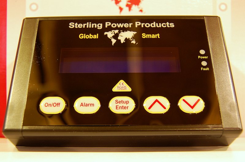
The remote for the Sterling Pro Charge Ultra offers a multitude of display options including monitoring DC output voltage, AC input voltage, DC current output, battery temperature. charger temperature, transformer temperature, total charging time, charging time this event and just about anything the charger is doing or has done. It is one of the most informative remotes I have seen on a battery charger, at any price point.
Wiring the remote is simple, four mounting screws and two plug & play phone jack type connections. It can be flush mounted or surface mounted and both options are included with the remote, plus the cable.
Please be aware that any battery type or voltage programming for the PCU needs to be done via the front of the charger. The remote display is data only, it’s not designed for programming the charger.
Marine chargers from companies like Sterling, Mastervolt, Victron, ProMariner & others will often have a remote display option.
Emergency!
We do not want to put this website behind a pay-wall!
Please make a donation, that’s all we ask. Your donations & affiliate purchases are all we have to fund this web site. Please help to keep MarineHowTo.com a FREE source of information!
 .!
.!
Just Say NO to Dip Switch Chargers
In today’s day and age there is less than zero excuse for a marine battery charger manufacturer to not offer more than three settings. Typical of far too many chargers all you get is three settings FLOODED, AGM & GEL.
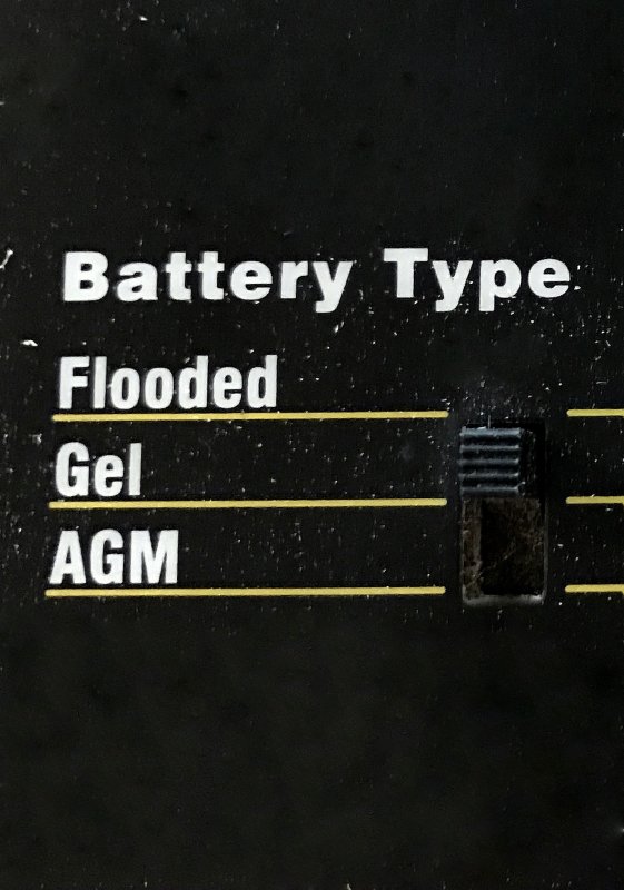
Unfortunately the voltage behind the words are very often not appropriate for your batteries. Dip Switch chargers, or as I often refer to them as “Dip Shit” chargers are an extremely poor choice in today’s market where recommended battery voltages are all over the map. Dip Switch chargers also very often lack temperature compensation. If your battery charges at 14.8V at 80F it CAN NOT charge at 14.8V at 100F!!
Battery Type is very often an Irrelevant Setting!
“RC, clearly now, you’re just a big freaking lunatic?”
I know that statement seems bold but please focus on what I am going to explain. What is relevant to your batteries are the battery manufacturers recommended absorption and float voltages.
As a boat owner, and battery manager, you need to stop looking at the words on a chargers pre-set Dip Switch list and instead look at the VOLTAGES behind the words.
AGM, GEL, Flooded, FDC etc. are words, and they mean absolutely nothing without knowing the VOLTAGES those words represent. One manufactures voltage for AGM will not always be the same as the next. For this reason you should only focus on the VOLTAGES the words represent. If the charger maker does not tell you the voltages, that the words FLOODED, AGM or GEL represent, WALK AWAY!
For some AGM batteries you will be much better served using the FLOODED setting rather than the AGM setting and vice-versa. Your batteries DO NOT charge by words they charge based on VOLTAGE. A charger should always be chosen to match your battery manufacturers recommended charging voltages. A charger offering a full user defined custom setting will always be able to match the manufacturers recommended absorption & float voltages where a charger with just two or three choices very often will not. If your charger cannot match the battery, then battery life and performance will suffer.
VOLTAGE is the key, not the words.
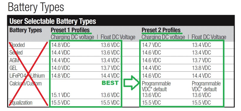
Ignore the WORDS and focus on the VOLTAGES
Just take a big red marker and cross out the Battery Types. Now that you’ve done that, find the voltage settings that match your batteries. Even with 11 pre-sets to choose from how well did you do..? Now imagine you only had two or three settings?
Let’s choose a charge profile for Lifeline AGM Batteries:
Manufacturer suggested charging voltages:
AGM Batteries – Which “AGM” Preset works?
Lifeline AGM’s = 14.4V & 13.4V = AGM Preset #1
Odyssey TPPL AGM’s = 14.7V & 13.6V = Neither AGM Preset
Firefly AGM = 14.4V & 13.2V = Neither AGM Preset
Mastervolt AGM = 14.4V & 13.2V = Neither AGM Preset
Full River AGM = 14.7V & 13.7V = Neither AGM Preset
Rolls AGM = 14.7V & 13.7V = Neither AGM Preset
East Penn/Deka = 14.6V & 13.6V = Neither AGM Preset
US Battery AGM = 14.4V & 13.4V = AGM Preset #1
Trojan AGM = 14.4V & 13.5V = Neither AGM Preset
This list, of manufacturer suggested voltage guidance, is why you should always buy chargers that have a custom setting. Even with 11 pre-sets only 1 out of 9 “AGM Pre-Sets” work for the Lifeline AGM’s. Once again please do not focus not on the words, but rather on the voltages.
Which flooded preset works for Trojan or Deka flooded batteries?
Trojan Flooded = 14.8V & 13.5V = Neither Flooded Preset is Idea
Deka Flooded = 14.7V & 13.8V = Neither Flooded Preset is Ideal
What do all these batteries have in common? They all ideally need a user customization voltage profile.
Just say NO to dip-switch chargers…
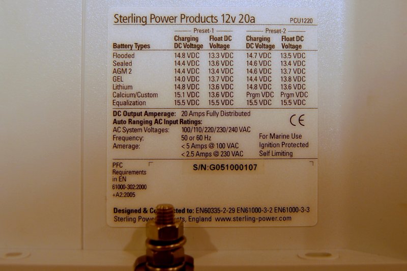
11 Pre-Sets and One User Programmable Charge Profile
The Sterling PCU packs a lot of features into this small form factor charger. Right out of the box it has 11 preset charging profiles. On top of the 11 presets it also has one custom profile that can be tailored for a battery not already met by the preset options.
There are very few battery chargers, at any price, that currently allow the user to build their own charging parameters. A very cool feature for those who may need it, like the owners of Lifeline batteries.
As an example Lifeline battery, the AGM battery manufacturer, wants to see 15.5V, temp compensated, for 8 hours to “condition” (equalize/desulfate) their batteries. Many other competitors chargers have an equalization setting of 16 volts for 1 hour or 16 volts for 4 hours or 15.5 volts for an hour etc. etc.. With the Sterling Pro Charge Ultra you can custom build a “conditioning” cycle that matches the Lifeline battery manufacturer suggestions or any other manufacturers suggestions if not already covered by the 11 preset. All equalization charges should be TEMP COMPENSATED so be sure your charger has a temp sensor if you’re going to be equalizing.
If you click the photo to make it larger you’ll see the 11 presets, and their voltages, plus the custom user profile.
Just Say NO to Egg-Timer Chargers
Seems like we’re saying no to a lot of things, and with good reason. First, let me state the obvious.

The ideal charge algorithm, for marine battery chargers, has not yet been implemented
Why?
In order to have an ideal recharge the charger really needs to know what is a house load and what is going to the battery. Seeing as battery chargers only know output current, or more accurately the percentage of its power supply being used, as well as voltage, they can’t have any idea what is flowing into the battery and what is flowing to house loads. This makes implementing a voltage only algorithm difficult at best. Some chargers use smarter algorithms and some use fairly dumb egg-timer type algorithms.
The Sterling ProCharge Ultra uses a number of factors to adjust and adapt the duration of the absorption cycle to what it believes the battery needs. In terms of charge algorithms it works pretty well. A simple explanation is that the ProCharge Ultra examines the duration spent in bulk and can then add or subtract time spent in the absorption stage. This type of algorithm is certainly smarter than a simple egg-timer. While not perfect, it does a better job at keeping the batteries healthy than do many egg-timer based chargers.
In an ideal recharge a battery charger would not drop to float voltage until the battery bank had attained the 99.5% to 100% SOC point. Almost all battery chargers out there, for marine use, drop to float before the battery bank has attained 100% SOC. While this makes them “safe“, for the manufacturers lawyers, it also means that in order to get back to 100% SOC it just takes a bit longer. At a dock this is not a huge deal, if we are getting into the mid to upper 90’s before the float transition. Once the charger drops to float this dramatically extends the time it takes to get to 100% SOC. The absorption cycle is perhaps the most important stage of charging and if it is too short, due to an egg-timer, the batteries can become chronically under charged and suffer the effects of sulfation.
Unfortunately far too many chargers out there work on the simple “egg-timer” principal. Here’s how an egg-timer charger usually works.
- Battery Charges In Bulk Stage Increasing Bank Voltage
- Battery Bank Attains Absorption Voltage Limit
- Once Absorption Voltage Limit is Attained a Fixed Timer Starts
- When Egg-Timer Ends the Charger Drops to Float
Hmm??
What if the batteries were already full when you booted the charger up and it now has a 4 hour egg-timer to burn through?
What if you began charging at 50% SOC and only gave the batteries a 1 hour absorption cycle? Even the best AGM batteries still require well over 3 hours of absorption charging, under ideal conditions, to get anywhere near 100% SOC from 50% SOC, even when being changed at rates as high as 40% of Ah capacity or 40A for a 100Ah battery.
What if the batteries are 50% discharged and it takes 5+ hours in absorption to attain 98-99% SOC and your charger has a 1 hour egg-timer?
One manufacturer even uses this egg-timer algorithm:
- Battery Charger is Turned On
- Four Hours Later the Charger Drops to Float Regardless of SOC
Oh and they call this “smart”..
Egg-timer algorithms are not smart, and in many cases can be unhealthy to batteries. Egg-timer chargers are the lowest form of “smart” you can actually get.
Charger Outputs
This 20A charger comes standard with three outputs which can be fed to three different banks. The output is distributed by demand not divided equally as some chargers are. So if a start battery was at 99% state of charge and your house bank was at 60% state of charge the house bank will be seeing the vast majority of the charging current and the starter would be seeing 1-2A or less.
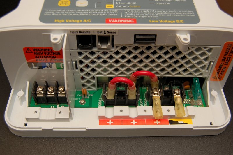
For owners who have a charge distribution system in place, such as an Echo Charger, Duo Charger, VSR (voltage sensitive combining relay), or in the US often referred to as an ACR (Automatic Combining Relay), the outputs can be “jumped” together as shown to create a simple “single output” charger.
Technically with this charger you don’t need to “jump” the unused outputs if using it as a single output charger. The US distributor feels, and I agree, that it is a wise idea to equally load the output FET’s so I chose to jumper than to even load the outputs. The two red jumpers are jumping output 1, 2 & 3 to load all the output FET’s equally. This essentially makes the charger a single output 20A charger rather than a three output 20A charger. All current in this installation will feed to the house bank and the starting bank will be charged via a Blue Sea Systems ACR relay. You would do the same with an Echo or Duo Charger.
This particular boat has an ACR / Automatic Combining Relay so the charger is being used as a single output. Keep in mind that nearly all chargers, with the exception of some very expensive ones, still only have ONE output setting, in terms of charge profile, so dividing it up is not really necessary unless you don’t have an ACR, Echo Charger or Duo Charger type of battery bank charge distribution.
Also note the location of the green fuse. This is the charger output fuse and it well located and easy to change if necessary.
The two heat shrink ring terminals are just illustrating where you can connect the neg and positive battery leads to.
It should be noted that on 30A and larger Sterling Pro-Charge Ultra chargers they use large studs as opposed to a small terminal strip for the DC output. I really wish the 20A model had these studs too but it does not. For that reason alone I would suggest considering the 30A or larger model if you can.
Choose A Location & DC Wire Sizing
The location your charger is mounted in plays a critical role in its life span & longevity. Care should be taken to follow your manufacturers instructions of orientation, access to air, moisture or battery gas exposure.
1- Mount the charger in a location were it can run cool and air can move around it. An engine space is often a poor location because the engines, and engine bay, remain warm long after the engine has been shut down. Many also have water heaters that can keep the temps in these small areas higher than average. While on many vessels you don’t have a choice in this matter, due to space constraints, always look for a location outside the engine space before installing there. If the charger has a fan be sure to mount the inlet and outlet in areas where they will have unobstructed air flow. If necessary, or prudent for your charger, you can cut ventilation holes in lockers, and then cover the holes with pre-made ventilation grills to allow air flow. Ventilation for your charger does not have to look bad. There are many grill options available from teak to stainless steel.
2- If your hull is a dark color it is best to avoid mounting the charger directly to the inside of the hull. Topside hull temps, in direct sun, with dark colors, can easily exceed 140F! I have one customer who’s AGM’s were dead every two seasons use, about 100 cycles, like clock work. He had done everything suggested by the manufacturer including installing solar for his mooring sailed boat to keep them at or near full charge. It was not until I measured the battery compartment temps at 133F, located behind the cabin settee seat back, that we figured out his failure mode. Just as heat is bad for batteries it is also bad for the charger. A cool running charger is a happy charger. If your chargers fan runs constantly it may be trying to tell you something..
3- Battery chargers should not be mounted in a battery compartment/space despite being ignition protected. Corrosive battery gas can damage the metals in the charger and lead to shorter life or corrosive damage. All lead acid batteries, WET, GEL and AGM have the potential to vent corrosive gas. Just because your battery is a VRLA design does not mean it won’t vent corrosive gas if over temped or over charged. A battery compartment is an absolute last resort location for a charger.
4- Try to find a location that is dry and will not have the possibility of water dripping on the charger. If there’s even a slight potential of water exposure a drip shield should be constructed to protect the charger. The drip shield should prevent water from damaging the charger, but also allow for proper cooling. This is not always an easy task so mounting in a known dry spot is always the best approach. Generally speaking, higher in the boat is often better than lower in the boat for a charger mounting location. Areas closer to the bilge, or with direct ambient access to the moist bilge air, tend to be more humid and corrosive environments.
5- Try to mount the charger as close to the battery bank/banks as possible without mounting in the battery or engine compartment. Shorter wire runs mean less installation cost, less voltage drop can make for better charger performance over the long haul.
6- The area on your vessel where the charger is mounted should be clean and free of oils, vapors or other sorts of contamination. While UL 1236/ABYC chargers are “ignition protected” it is not recommend to install them where any gas vapor can accumulate. This includes LPG, gasoline, hydrogen gas or where stored solvents could spill & leak.
DC WIRING
The DC wiring is a very critical part of a chargers performance. Most manufacturers want to see a maximum voltage drop of between 1% & 3%. Voltage drop is determined by the amperage flowing through the cable over the round-trip length of the circuit. This means you add the full length of the negative and positive wires, plus the max amperage that will flow, to determine your voltage drop.
This 20A charger was wired up for less than a 1% voltage drop using 6GA wire. I personally prefer as little drop as possible. Realistically I could have easily wired this with 10GA wire and been at 2.75% voltage drop but Sterling ideally wants to see less than that and I don’t always stock 8GA wire, so 6GA it was.
A 3% voltage drop at 14.6V is roughly 0.44A of lost voltage between the charger and battery bank. This can potentially leave you with a charging voltage at the battery of just 14.14V. With DC charging sources bigger wire is almost always better.
Just say YES to On Battery Temp Sensing
This is the Sterling ProCharge Ultra’s on battery temp sensor. The supplied sensor is 10′ long, but it can easily be extended with a typical 6P2C male to female RJ11 phone cable or with an RJ11 in-line coupler.
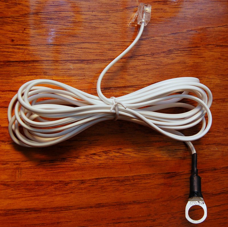
The sensor is using the two middle terminals as would the typical red & green two wire phone cord. Here’s a hint though, if you need to extend the temp sensor you’re likely going to need much larger gauge positive and negative output cables. Try to keep the charger as close to the batteries as you can without physically being in the same compartment.
Temperature sensing of your batteries is very important to the longevity of a bank, especially with valve regulated lead acid batteries such as AGM, TPPL AGM or GEL. The hotter the climate you are in the more important temperature compensation is. Temperature compensation is more critical as temperatures rise rather than fall but both are important. As the battery temperature goes up, the battery charging voltage must come down. As battery temperatures drop the charging voltage can go up. The ProCharge Ultra is a fixed temp coefficient, meaning it’s not user adjustable. The temp coefficient is 0.013mV up or down per degree C change in battery temperature. This is a suitable temperature adjustment for most lead acid batteries, if a bit on the conservative side.
STORAGE WARNING: For batteries in long term winter storage, in colder climates, I am a proponent of physically unplugging the temperature sensor from the RJ11 port on the charger. I do not like to have unattended batteries having the voltage compensated UP while they are sitting there doing nothing all winter. They only need enough voltage to maintain 100% SOC and a standard float voltage will do this. It is important, if you want to do this, to physically unplug the sensor from the charger itself not just remove it from the battery terminal. Removing the sensor from the battery, but leaving it plugged into the charger, will still result in voltage being compensated UP, all winter.
In cold climates where you are physically using the batteries regularly compensating UP is good. For storage, I am not a big fan of it. In my opinion the best option for cold weather storage is to fully charge the batteries and then physically disconnect them from the vessel, chargers and from one another. This is the safest storage option. Unattended chronic float charging is just an “oops” waiting to happen.
If you are storing in a hot climate, above 75F then you really must leave the sensor connected. Heat is one of the major enemies of all batteries. If you have them in an engine room, which is not advised, or you live in a warm climate, you really do need a charger that features on-battery temperature compensation to reduce the charging voltage when the batteries begin to heat up. If your batteries can regularly exceed 80F then you’ll need a charger with temperature compensation.
It’s Not Just Ambient Temperature
While charging voltages need to be adjusted for ambient static battery temp, the act of charging and discharging can also create heat and the need to adjust charging voltages during charging for heat created internally in the battery.
Earlier versions of temp compensation on some chargers was sporadically successful at best, bordering on dumb, as in not very smart. With newer technologies these sensors can be accurate to within a degree or two, which is more than enough.
Any charger that does not offer ON THE BATTERY temp sensing is simply not a smart charger.. Beware that many charges that claim “temp compensation” are doing this via ambient temperature at the charger itself. Ambient temperature sensing CAN NOT identify battery heating due to the effects of charging or discharging. If the charger is in a cool spot, and the battery bank is in an engine bay, you can literally cook your batteries. Ambient temperature sensing is NOT SMART…
Sadly the term smart charger is bandied about these days like a ping-pong ball. I think Deka / East Penn, one of the largest US battery manufacturers, cautions us very well on so called “smart chargers“.
Begin Quote:
Deka / East Penn Battery
“Unfortunately, many chargers on the market claim to be gel/VRLA “friendly” or “OK for sealed batteries”, but are not. Some overcharge the batteries, while others may not fully charge the batteries. Some chargers claim to be “smart”. Some “smart” chargers do a good job, others do not. The best choice of charger often depends on the application.
Almost all applications require temperature sensing and voltage compensation. Beware, many chargers measure the ambient temperature which could be significantly different from the battery’s internal temperature.”
End quote:
Battery Temperature Sensor Location
In this picture you can see the location of the battery temperature sensor.

It is important to mount the sensor directly to the battery post or battery case so it senses the temperature of the bank correctly. A temperature sensor should be mounted to the battery which has the most potential to get warmer than the others. For example, if your battery compartment backs up next to an engine room bulkhead the battery closest to that bulkhead would get the temp sensor.
Any terminal mounted temperature sensor also needs to be connected directly to a negative terminal, and not the positive terminal. The temperature sensor has the ability to fry the charger if connected to the + terminal and also the potential to be accidentally shorted. A battery temperature sensor can not be fused and still sense temp correctly. If following the applicable safety standards, such as the ABYC standards, a temperature sensor can not be connected directly to a + post.
Always keep in mind, when stacking terminals on a battery post, that the highest current potential terminal is always placed on the bottom. In this case the two 2/0 negative cables go below the temp sensor ring terminal. There is also a limit of four terminals per battery post. Use buss bars if you need more than four items on a battery post.
ABYC standards now also prohibit wing nuts on battery terminals if any wire connected to the battery is larger than 6GA AWG. Use standard nuts with locking washers or nyloc nuts if you have enough thread left for the nylon in the nyloc nut to thread over.
Charger Feed Wiring
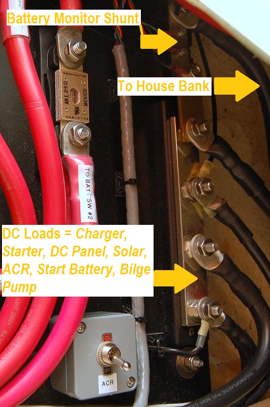
In this photo you can see how the charger is feeding the bank. With banks in parallel or series parallel it is important that the charger supplies it current across the bank. If you look you’ll see that the positive feed and the negative return pull off opposite sides of the battery bank.
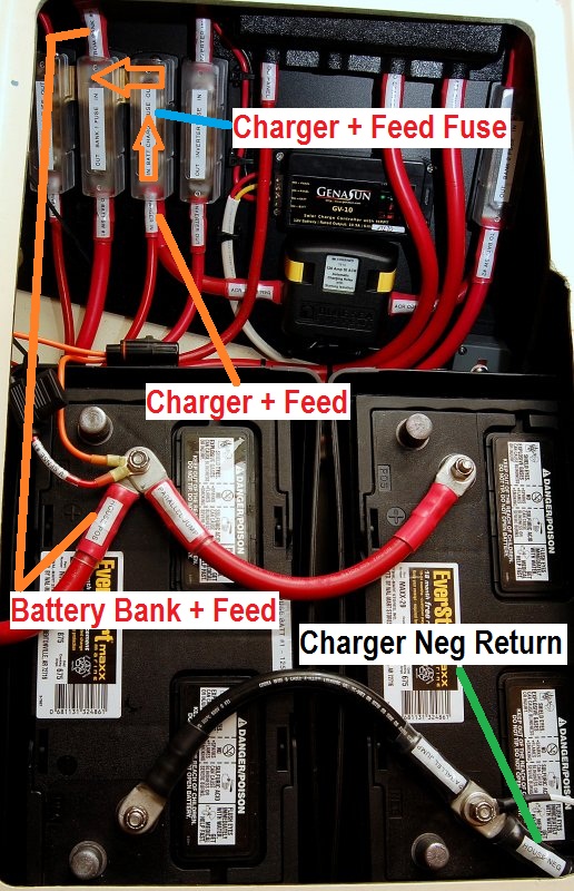
Wiring this way forces the current to flow through the entire bank and helps to minimize any intra-bank imbalances. This is one of the most often violated rules of charging I witness on boats. It is important to note that this is not just for charging sources such as chargers, alternators, wind or solar but also for the DC loads. Always connect across your bank to keep intra-bank imbalances to a minimum. As banks get larger there are more precise ways of wiring that can lead to better balancing but doing it this was gets you a lot further ahead than pulling everything off one end.
You will also note the three bused ANL fuses on the left which protect the ALTERNATOR, HOUSE BANK and CHARGER wiring. The ABYC requires that any device connected directly to a battery be fused within 7″ of the + battery post to protect the wiring. These fuses are not intended to protect the devices but rather the wiring in the case of a dead short to ground. While the 7″ rule is often very tough to meet always try to get the fuses as close as you can to the battery + post. The wire marked HOUSE BANK + FEED is about 16″ long but runs in a conduit for about 9″, under the quarter berth, then comes out at the fuse.
Because the alternator and charger do not use the same size wiring as the house bank feed to the battery switch, they each need their own fuse to protect the wire.
When you parallel banks you add or combine the amperage as in Ah’s, cranking amps or short circuit amperage. These group 31 wet cell batteries can pump out in excess of 1200 cranking amps at 70F. For just two of these batteries that is 2400+ amps of cranking current at 70F.
The short circuit current is always multiples higher than the cranking amperage at 70F. Marine Cranking Amps (MCA) are rated at 32F and Cold Cranking Amps (CCA) are rated at 0F. As temps drop you have less available cranking ability and as the temp climbs the more cranking & short circuit ability you’ll have to fry things. 2400 amps is enough to weld metal with and that is not even the short circuit rating.
Fuse Bus
This is the fuse distribution bus discussed in the last photo.
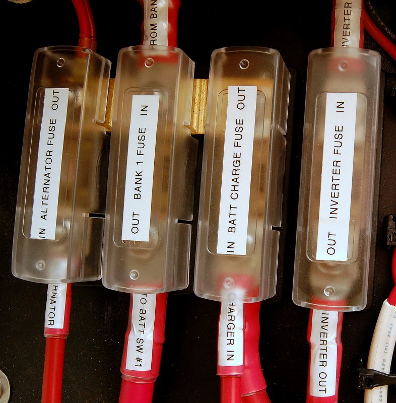
The three ANL fuses are bused together with copper bar stock at the top of the fuses. The source wire from the house bank comes in the top and the ALTERNATOR, BATTERY SWITCH FEED, CHARGER/ACR are protected out the bottom.
There are many ways to fuse devices and banks like this. For this application I found the bused ANL fuses a good fit.
Close Up With Covers Removed
This photos shows the ANL fuses and buss bar. Just makes it easier to see.

One of the benefits of a charger like the Sterling is that you can use the charger as a 12V power supply if you disconnect or remove your batteries from the boat during off-season layup.
Wiring the charger direct to hard mounted buss bars and fuses, and not direct to the battery posts, means it can still power the vessels DC system even with the battery bank is disconnected and off line.
Parallel Batteries – Optimal Hook Up
This illustration will better show how to connect charger sources and loads to your battery bank.
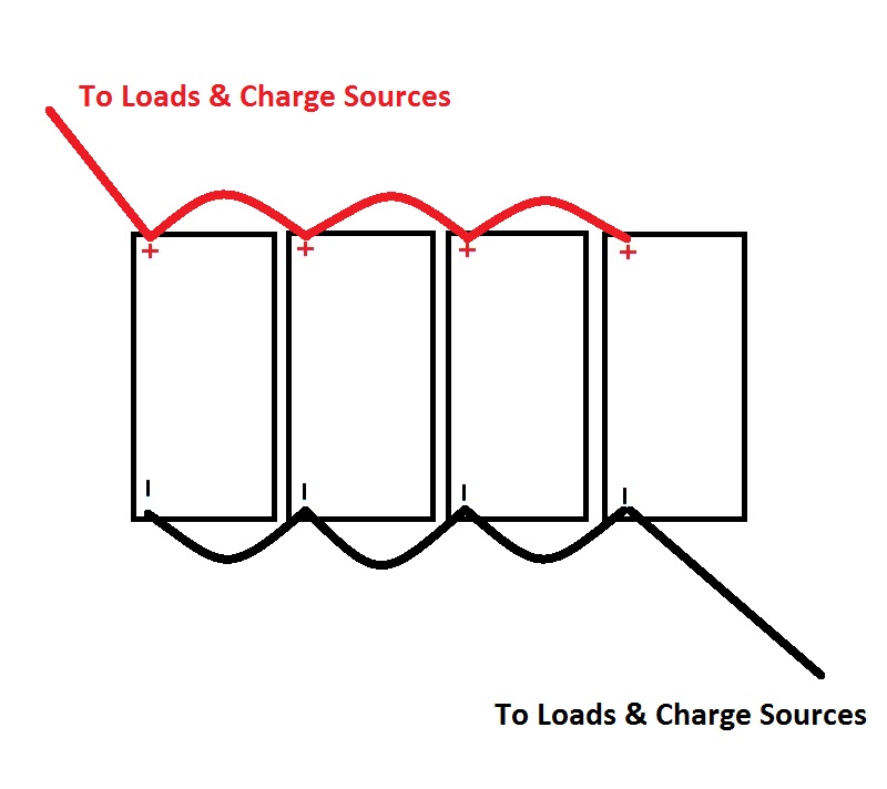 In most applications, it will be most optimal for battery balance, to connect across the bank. This will force the batteries to charge & discharge more evenly and uniformly and over the life will help to keep them in better balance.
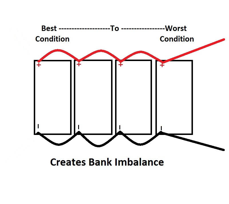
Parallel Batteries – Less Optimal Wiring
I have used our shops battery testing equipment many times in scenarios like this, and in every example, I see the bank unevenly balanced. The batteries show these imbalances during testing. In a bank of batteries, wired like this, it does matter, over time. Don’t just connect your charge sources or loads to one end of a bank.
 Of course you don’t need to take my word for it, this is what Odyssey Battery (EnerSys) has to say about properly connecting batteries in parallel:
“Typically the positive and negative leads to the load are taken from the same battery; usually the leads from the first battery are used. This is not a good practice. Instead, a better technique to connect the load is to take the positive lead from one end of the pack (the first or last battery) and the negative lead from the other end of the pack.“
End Quote:
Negative DC Wiring
The bottom negative wire on that buss bar is for the battery charger. If your boat is equipped with a battery monitor, the chargers DC negative wire must be placed on the load / DC system side of the shunt as is shown here.
Wire The Temp Sensor & AC Wiring
In this photo I have plugged in the temp sensor and am testing the charger to see if it recognizes the temp sensor. It did.

With the Sterling Remote Panel the charger will tell you the battery, charger and transformer temp to within 1 degree. A pretty cool feature.
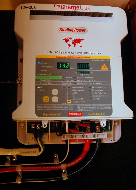
The AC wiring should be sized based on the manual for your charger. For this charger it calls for 14/3 AWG AC colored wire. The input for the AC wiring is marked L – N – G or BLACK/HOT, NEUTRAL/WHITE & GREEN/EARTHING GROUND.
Your charger should ideally have it’s own dedicated breaker in the AC panel sized to protect the AC wire you’re using. It is not suggested to share a breaker with any other device for a fixed mounted charger. This one uses a 15A breaker and 14/3 AWG AC color coded wire.
Always install your AC & DC wiring to acceptable color code standards. For AC and a single phase charger like this it is:
Green = GROUNDING/EARTH
Green = BONDING or EARTHING
Wiring Up The DC Side
In this picture I have mounted the charger to a back board which will get mounted to the boat.
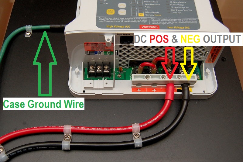
The wires are affixed to the board with sufficient strain relief to prevent inadvertent loading of the attachment point to the charger. The ends of the wires are crimped with ring terminals using the proper tool and then sealed with adhesive lined heat shrink. I also coat the lugs with a terminal grease to prevent oxidation/corrosion at the lug/terminal strip interface.
One of the more critical aspects of charger installations, that I nearly always see violated, is the green case ground wire shown. If I had to guess I would say that nearly 85% of the installations I see are either not case grounded or the case ground wire is to small.
This green grounding wire grounds the chargers metal frame to the vessel and allows your over current protection devices to work properly, if there is an internal fault that shorts to the case.
A fault in the DC side can supply enough current to overwhelm and overheat the AC green grounding wire. It can even do this well before tripping a fuse or breaker. It is a must do requirement that the case be bonded/grounded/Earthed with a green wire of not less than one size smaller than the DC conductors!!
This green wire gets sized for the DC side of the charger. The green AC ground will not satisfy the ABYC case ground requirement on an AC/DC battery charger. Follow me on this one. If there is a fault on the DC side of the charger the AC green wires size may not be able to handle this fault and could be undersized in having to handle that fault. This is why the requirement for the chargers case ground is for no less than one size smaller than the DC output wires.
The ABYC standard suggests that the case ground for chargers needs to be no less than one AWG gauge size smaller than the DC output wires. So, if you have 6 GA DC wire then you need no less than an 8 GA case ground wire. Even if your wire is already technically “over sized” your surveyor or insurance company may not know this so it is always best to wire it equal to or no less than one AWG size less than the DC output wires.
Test & Program Your Charger
It is always a good idea to check with your battery manufacturer and obtain the recommended ABSORPTION, FLOAT and EQUALIZATION voltages.
You will then program your charger to your batteries using the preset charge algorithms. Some chargers offer very little in the way of “smart” charge programs, sometimes four or less, and others, like this Sterling, offer plenty of options. As mentioned the Sterling PCU chargers also offer a user defined program that you can self program. Very cool for those applications that need it.
You can always choose to use GEL or AGM settings on wet cell batteries but a good quality charger will not go into equalization mode, and should not, while in AGM or GEL mode. If charging WET batteries with a GEL or AGM program you’d need to switch back to a WET program to equalize your batteries. In contrast you should NOT use AGM or WET settings on GEL batteries.
What Are BC Mode and PS Mode?
A number of years ago the State of California mandated that battery chargers were no longer allowed to float charge batteries. Once charged the charger needs to stop charging or even floating the batteries and go into a sleep mode. The Sterling ProCharge Ultra ships in BC mode (BC = Battery Charger). When California mandated this, the ProCharge Ultra’s original BC mode became the new CEC (California Energy Commission) compliant mode. For owners who do not want to use the charger as a CEC compliant charger, this can be easily changed by selecting PS mode during the chargers boot-up period.
There is some confusion on the net regarding exactly what PS mode (PS = Power Supply) actually does. Some folks incorrectly assume PS mode is a constant float and lacks bulk the absorption stages. PS mode is not a constant float and it will do BULK, ABSORPTION & FLOAT. What it will not do is go to sleep, after float, as California would prefer.
The video below should help to clear up any confusion on this subject.
A Few Words on Equalization:
Sulfation is like cancer of the battery, once it has set in it is only a matter if time before the battery passes on to battery heaven. Equalization is like chemotherapy. It helps prolong the life but only prolongs the inevitable for some time. Please do not over equalize your batteries as it can cause plate decay and lead to shorter life if over-done. On the flip side don’t be affraid to equalize when signs are present that you need to. The best thing you can do for your batteries is keep them at or near 100% state of charge as often as possible using the highest safe absorption voltages allowed by your battery manufacturer. If you’re on a mooring this will require wind or solar, an alternator simply won’t do this, and the batteries will sulfate prematurely.
I much prefer to equalize batteries one at a time and monitor the progress with a hydrometer or, what I use, a sight refractometer. A good charger with temp sensor should monitor the temp but it never hurts to have a digital infrared thermometer on hand while equalizing. Please DO NOT equalize batteries unattended! It is very wise to be there during equalization. If you are unfamiliar with equalization PLEASE research this before hitting the button. To equalize one at a time simply disconnect the batteries not being equalized.
Thoroughly test your charger before leaving it to do it’s thing. I personally don’t like “unattended” charging even with the best built chargers in the world. This is just MY personal preference, so consider it, but don’t take it as gospel. For unattended charging I use solar. It works for us, but may not for you.
Unfortunately for many boaters in warmer climates, with WET cell batteries, the ambient temps require that chargers be left on and most often “unattended”. This is due to the exacerbation of battery self discharge in warmer temperatures. Heat kills batteries, cold helps prolong life.
Sulfation and self discharge greatly accelerate the warmer battery temps are, so do keep your batteries topped up as often as you can. In a perfect world all chargers would perform flawlessly for 20+ years. Sadly for the boating public we don’t live in a perfect world and many a charger has taken out a perfectly good bank when it decided to pack it in, we see it far too often. When owners leave a charger on constantly, while the vessel is unattended, a charger failure can go unnoticed until it is too late. It can sometimes take the batteries out with it. A simple unattended charger failure now becomes an entire new bank and a new charger as opposed to just a charger. If you don’t need your charger on constantly, consider not leaving it on while it’s unattended. Balancing unattended charging & its potentials for failure modes, versus the potential for self discharge and the resulting sulfation is one you’ll have to tackle on your own.
Simple Guide to Follow When Purchasing a Marine Battery Charger.
Does It Have?
Temperature Compensation – If Not – DO NOT PURCHASE IT
UL Marine Marine 1236 – If Not – DO NOT PURCHASE IT
The Ability To Be Programmed for Your Batteries – If Not – DO NOT PURCHASE IT
A Smart Algorithms – If Not – DO NOT PURCHASE IT
An Equalization Feature – If Not – DO NOT PURCHASE IT
World Voltage Capability – If Not – DO NOT PURCHASE IT