Regulator Sensing Voltage at Alternator End
The topic of wiring a high performance alternator regulator, and doing it correctly, comes up a lot. One of the most confusing and often misunderstood areas, that can bite into your charge performance, is incorrect voltage sense wiring. This short article deals only with correcting voltage sense wiring mistakes for the Balmar MC or ARS regulators as well as the discontinued Xantrex XAR (made by Balmar).
With a high performance voltage regulator, such as the older Balmar MC-612 or current MC-614, and some others, they include a dedicated voltage sensing circuit. This is a great feature, if you wire it correctly..

NOTE: The Balmar ARS-5 and Xantrex XAR regulators do not have a dedicated positive volt sensing lead. On these models voltage sensing is done between regulator B+ (red) and regulator B- (black). If these wire runs are extended to the battery bank care must be taken to account for the voltage drop in the red wire which can carry as much as 6A +/- to drive the field current. For the best performance you’ll want voltage drop in the regulator B+ wire to be as close to zero as possible. If you’ve not already purchased a regulator, then consider the Balmar MC-614 for it’s added positive voltage sensing wire..
A voltage sensing circuit is a circuit intended to carry minimal to no current so there is minimal voltage drop in this measurement circuit. The voltage sensing circuit should really be considered a voltage correction circuit or a voltage drop compensation circuit.
The voltage sensing circuit works by utilizing these smaller sensing wires in order to compensate for the voltage drop in the larger alternator output wires. The larger alternator positive & negative are actually carrying the high current and even if large will suffer from some voltage drop. Voltage sensing is supplied on these high performance alternator regulators so we can achieve the correct regulator set point voltage, at the battery itself, not just at the back of the alternator. These sensing wires measure the actual battery terminal voltage and allow the regulator to drive the voltage at the battery end to the correct point.
Voltage is the pressure that allows current to flow into the batteries. Incorrect voltage sensing causes your regulator to prematurely begin limiting voltage. Once voltage is held steady current has to decline in order to not over shoot the voltage limit of the regulator. The issues of voltage drop and incorrect voltage sensing leads to longer charge times. Sail boats, more so than power boats, simply want to pack as much energy back into the bank and do so in the shortest time possible. If you have incorrect sensing this can rather dramatically cut into how much capacity you can return in a given period of time.
The voltage drop numbers seen in these three illustrations are the actual voltage drops measured on a boat I worked on two years ago. The alternator output wires, both positive and negative, according to the owner, were sized for a 3% +/- voltage drop. However terminations, fuses etc. were not accounted for in the voltage drop calculation and the length wound up a bit longer than anticipated in the owners original calculations.
In this illustration we have the alternator regulator prematurely limiting voltage to 14.4V because it is sensing the voltage BEFORE THE VOLTAGE DROP OCCURS.. The alternator volt sense circuit is seeing 14.4V, at the alternator, and the regulator is now limiting or holding the voltage steady at 14.4V. Now take a look at what is going on at the battery end. At the battery end the voltage is just 13.79V and considerably less current can flow into the bank at 13.79V than it can at 14.4V.
If you are buying a high performance alternator and regulator some of your performance improvements come from the alternator no longer being what is referred to as “self sensed”. Part of the performance improvements, when moving to external regulation, come from the ability to directly sense the battery terminals, instead of the back of the alternator.
“But RC it’s only a 3% voltage drop?”
While 3% sounds good, 3% on a voltage limit of 14.4V = 0.43V drop. This wire drop is on top of any terminations or fuses these wires pass through on the way to the bank. The net result is an alternator regulator limiting voltage to 14.4V and the batteries seeing just 13.97V. That .4V makes a big difference in how much current your batteries can take at XX SOC…
“But RC as current declines, when the battery approaches full, there will be little to no voltage drop. The batteries will eventually get to target voltage, so what’s the big deal?”
Yes, this thinking is in-fact correct. However there are a few issues with it.
#1 Yes, voltage drop is directly related to the current flowing through the wires. In an ideal world we’d have all the time we’d want, or need, to charge the batteries. With cruising boats we simply don’t have this time or the luxury of 10+ hours to do this. For the reasons of time alone voltage drops, in system wiring, cut into the charge speed of the high performance system you just paid buku bucks for.
#2 Once the regulator attains 14.4V+ the time clock or cycle algorithms begin running on the absorption cycle. Batteries need a good absorption charge cycle for optimal health. If the regulator is dropping to float just about the time the batteries physically come up to 14.4V+, due to the incorrect voltage sensing issue, we really get a shorter and poorer absorption cycle despite the regulator thinking the bank did. This, compounded on the many other charging problems I see, can lead to chronic undercharging. An inadequate absorption cycle can result in the effects of sulfation setting in sooner than it should.. With voltage drop the regulator has been in what it thinks is absorption for longer than the batteries have. Think about this. Incorrect placement of the voltage sensing wires is easy to address and fix with external regulation.
If you think voltage sensing impacts lead acid batteries in a bad way, the impact on LiFePo4 batteries, a very fast growing technology, can result in almost no charging performance at all, when you have too much excess voltage drop.
Don’t let your regulator enter absorption before your batteries get there!!
Regulator Volt Sense to Battery – Positive Side Only
In this illustration I have run the regulators dedicated positive voltage sense wire direct to the house bank. As we can see the regulator is now compensating by 0.29V. This is the voltage drop in the alternator outputs positive wire. The regulator is now producing 14.69 volts, across B+ & B- in order to get what it thinks is 14.4V across the voltage sensing circuit.

Because we have not completed the voltage sensing circuit, and the negative wire is still connected to the back of the alternator, we have not compensated for all the voltage drop, only half of it.
I know, I know “Balmar says to connect regulator negative to the alternator.”
What they actually say is this:
“In most applications, this wire can be connected directly to the alternator’s ground terminal post.”
For a cruising sailboat they are giving you very general information in this regard. The key word in that sentence is “most”. Heck most boats in this country are power boats who run engines long enough for incorrect voltage sensing to not matter as much. If you own a trawler or power boat you probably fall into this “most applications” scenario. However if you want to run your engine for a maximum of 1 hour per day, and get the absolute most from your charging system in that time, then you really don’t qualify for the “most applications” discount….
If you pick up the phone, call Balmar, and talk to Dale etc. they will confirm exactly what I have just shown you here. It simply needs further clarification in the manual for those who want the utmost in performance..
Positive & Negative Regulator Volt-Sense to Battery End = Correct
Finally we now have correct voltage sense wiring. As can be seen the regulator is now driving the alternator to 15.01V in order to have 14.4V at the battery end. The voltage sensing circuit on Balmar and the Xantrex XAR regulators is a CIRCUIT. This means the red wire and the regulator negative wire both need to see battery terminal voltage for optimal performance.

NOTE: In the spirit of simplicity of the illustration these drawings lack an alternator output fuse. This fuse would be within 7″ of the battery banks positive terminal. They also lack a positive volt sense wire fuse, also within 7″ of the battery banks positive terminal…
Get all the speed & charge performance you’ve paid for by wiring your alternator positive & negative output direct to the house bank. After you’ve done that wire the volt sensing circuit direct to the positive and negative bank terminals as well. Like anything it’s all in the little details..
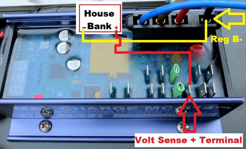
Balmar MC-614 Voltage Sensing Terminals
These are the actual terminals used by the Balmar MC-614 regulator to make the voltage sensing circuit work. It requires both the regulator B- terminal and the + volt sense terminal to get accurate voltage sensing.
“But RC, the black wire in the regulator harness is powering the regulator and field current so it will have voltage drop.”
While I like the way this reader was thinking, I can explain why this thinking misguided. The regulator black wire in the “Ford Plug” is not carrying the negative field current. The field current, on the negative side, is carried by the alternators B-/Neg. The red wire in the Ford harness supplies positive field current and it returns via the alternator B- not the regulator B-. On average, with a typical marine alternator at full field, we measure 0.1A to 0.3A on regulator B-/Black. On the standard Balmar harness this amounts to roughly a 0.03% voltage drop.
If you extend the harness you can always bump the wire gauge but with so little current carried on regulator B- it is easy to see why voltage sensing is so vastly improved by moving regulator B- to the bank being charged.
No Voltage Sensing at Battery – 1 Hour Charge
In order to try and show what the impact can be on a high performance charging system I set up to recreate a scenario I had on a customer’s boat.

This was a race boat and light and fast was the game. As such the bank was designed to be cycled to approx 35% SOC as opposed to 50% most cruisers would do. The cost of the batteries was not the issue for this owner. Battery weight and getting as much energy back into them, in the shortest time was the main goal. He chose TPPL AGM’s (thin plate pure lead) for their ability to take a high charge current rates yet he was not happy with how long his batteries were staying in bulk.
With a .5C charge capability on-board (.5C = 50% of bank Ah capacity) and Odyssey TPPL AGM batteries he should have been doing better than he was. I ran his alternator in bulk charge and measured a .73V drop from the alternator end to the battery end. Not a good find on a boat demanding the utmost in fast charging…. I fixed this issue by addressing the placement of the voltage sensing wires and beefing up both the positive and negative alternator output wires.. Performance increased, and all was good.
For this article I took a brand new Odyssey PC2150 battery (Group 31 12V AGM), that I had just tested at 100.2Ah’s of capacity at the 20 hour rate.. I then discharged the bank down to 11.85V at 77F and the 20 hour rate of 5A. This left the battery at 35% SOC or about 65% discharged. The battery was then recharged with an approx .7V drop at 50A. I set the charger for a 14.7V absorption voltage. The results are in the graph above. Click on the graph to make it larger.
Points to Ponder:
*In 1 hour of charging, at a .5C charge rate, the battery never exceeded 14.3V.
*At just 14.0V, measured at the battery terminals, the charger began limiting voltage. When measured at the charger end, it was seeing 14.7V and it began holding the voltage steady.
*Once the voltage is held steady current tapers off and charging speed reductions are happening.
*Maximum bulk time was limited to 30 minutes at 50A, due to the voltage drop. This resulted in just 41.93 Ah’s delivered to the battery in the 1 hour recharge period.
Voltage Sensing at Battery Terminals – 1 Hour Charge
Do you think it looks a little different with good voltage sensing..?

*In 1 hour the charge source delivered 49.37 Ah’s to the battery. This is an improvement of 7.44 Ah’s in just a short 1 hour charge cycle. This equates to a percentage increase in charge performance of approx 17.7%, just by moving two small wires.
*Bulk charge, at 50A, increased by 20 minutes to a full 50 minutes of bulk charging. Remember this was a 100Ah battery charged at 50A for just 1 hour.
*The battery actually attained the absorption voltage set point of 14.7V. This is healthier for the battery than stopping at 14.3V. It can help limit some of the effects of sulfation, even in a short 1 hour recharge.
*In the previous test, with no voltage sensing, that battery would suffer performance issues considerably faster due to never even attaining the 14.7V target with daily 1 hour recharges.
Note: Every system and battery bank will perform differently and these graphs may not be representative of the system on your boat. As batteries age the charge acceptance ability diminishes and they will attain absorption voltage faster & easier and will thus begin limiting current sooner in the SOC range.. Getting a good long absorption cycle, with the correct terminal voltage, is but one piece of the battery charging puzzle and good voltage sensing circuit can help with this.
Voltage Sense Wiring Blunders
We’ve discussed the importance of good voltage sensing, in relation to charging performance, but it is not always as easy as it appears.. Let me try and sum it up in one line..
YOU CAN ONLY SENSE VOLTAGE AT THE BATTERY TERMINALS IF THE ALTERNATOR IS ALSO CONNECTED TO IT!!!
I know some will still not understand what that means so we are going to delve deeper. Unfortunately I see and correct this blunder far more than I ever should and this one is a battery destroying blunder.
On the typical factory wired boat the alternator output, also called B+, is wired over to the big post on your starter motor. From there it picks up the large wire that comes from the “C” post or “common” post of your 1/2/BOTH battery switch. This is how the alternator gets current to your batteries, by sharing the same wire the starter motor uses.
This method of wiring a factory alternator is cheap, easy and saves the builders lots of money. Some builders do a better job and do direct wire the alternator to the house bank but these are usually high quality builders, not your average production builders.
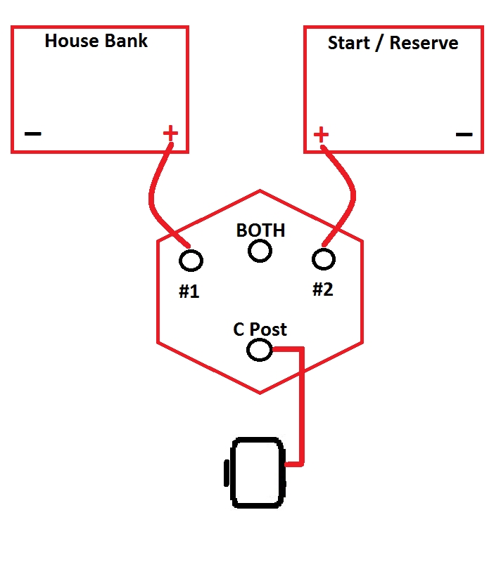
In this overly simplified illustration we simply have the alternator wired direct to the “C” post of the battery switch. It is easy to see how the battery switch becomes a charge directing switch in this scenario.
Set it to #1 and the alternator charges bank #1
Set it to #2 and the alternator charges #2
Set it to BOTH and the alternator charges BOTH
Now what happens if we add a high output alternator, and leave it wired this way? What happens if we leave it wired this way and then run volt sensing to the house bank??
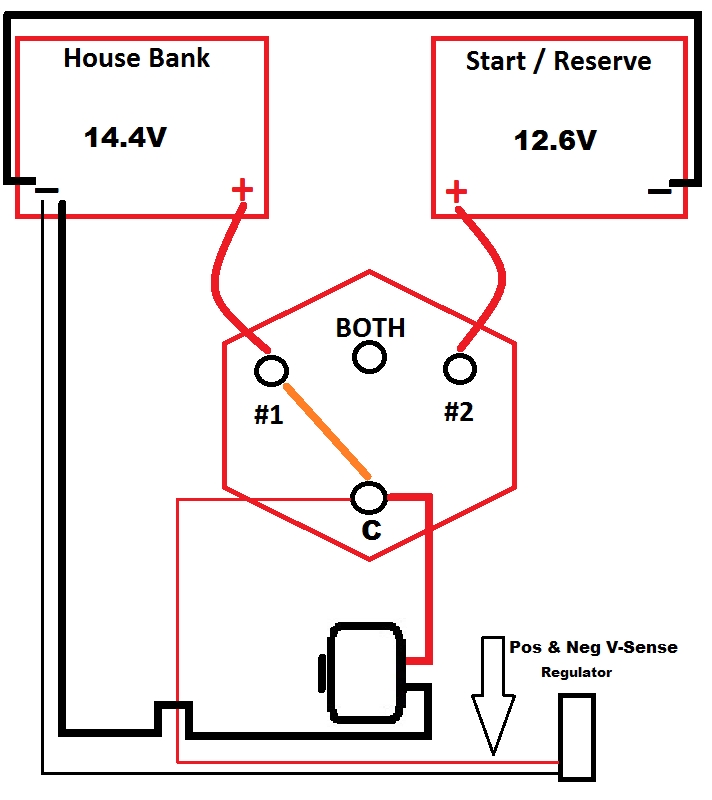
Volt Sense Wiring Blunder – Charging House
Okay in this illustration everything appears to be working fine, and so long as we never move the switch to #2, it will be..
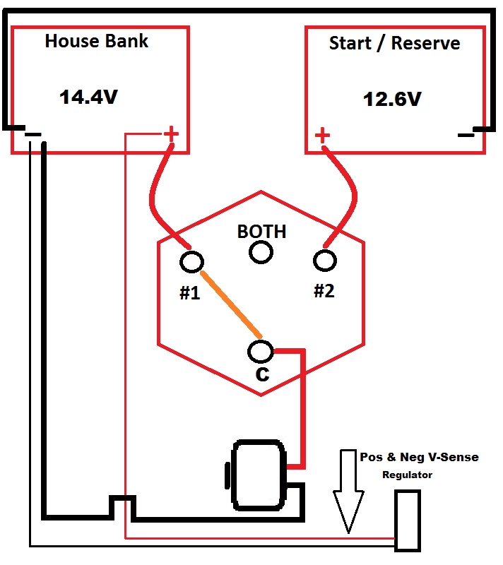
The Lifeline AGM battery is at its target voltage of 14.4V and is getting charged via the 1/2/BOTH switch directing charge current to the HOUSE bank denoted by the orange switch line to position #1.
In this scenario the HOUSE comes up to proper voltage and everything works. HOUSE at 14.4V START at resting open circuit voltage of 12.6V or so.
NOTE: This diagram assumes no Echo Charger, Duo Charger or Combiner to charge bank #2..
Volt Sense = FAIL !!!!!
“Mission control, we have a problem”… Follow the orange line and try to figure out where we’ve made a mistake?
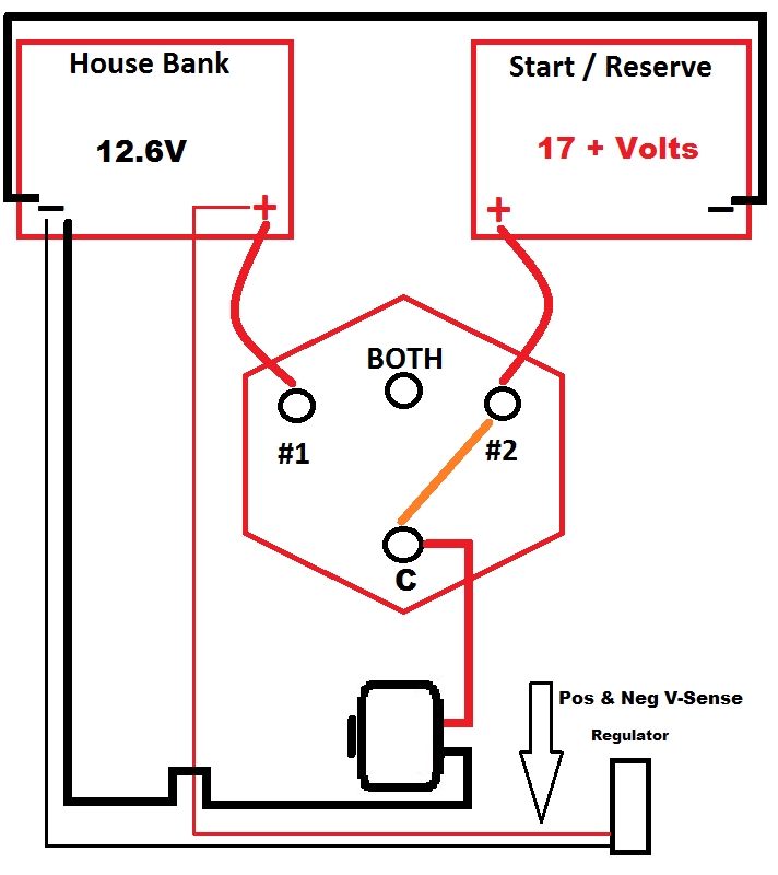
#1 The regulator is sensing voltage at the HOUSE bank and waiting to see a change.
#2 The alternator is feeding directly to the START battery but the voltage being sensed by the regulator is not budging, on the house bank, and why would it?
#3 In this scenario the regulator remains in FULL FIELD (full output mode) driving the voltage of bank 2 through the roof! We have an alternator being told to stay in bulk charging and a START battery that was nearly full to begin with. The result is the bank 2 voltage rising uncontrolled and frying the battery.
I have seen far too many batteries destroyed by this particular blunder over the years and the manuals apparently do not make this clear enough, for all installers.
Volt Sense = Correct
If you must leave your new high performance alternator wired through the 1/2/BOTH switch then this is the correct wiring for the voltage sensing.
#1 Negative regulator or regulator B- goes to HOUSE bank negative terminal.
#2 Positive volt sense goes as close to the bank as it can be without the ability to decouple voltage sensing from the bank receiving charge current. This means the “C” post of the battery switch is the absolute closest you can get to the battery terminals and be safe.
Is this ideal? No, but if you choose to leave the alternator output/B+ wire passing through the starter cable, via the “C” post of the battery switch, this is the best you can do without toasting the start battery, at some point in time.
Service Disconnect Switch
When you do wire your alternator direct to the house bank please consider installing an alternator service disconnect switch. A service disconnect switch is a switch placed visibly in the engine space, and clearly labeled, so a service technician can isolate the alternator from the battery bank, while working on the engine, without having to remove a fuse to do so.
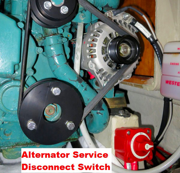
This is a Blue Sea Systems m-Series #6006 battery switch in the positive alternator feed. This switch is rated for 300A continuous. During normal use this switch always remains in the ON position. The only time it is turned off would be when a service technician is working on the engine. I prefer to mount this in the engine space so it is out of sight and out of mind of guests on-board who are; “just to trying to help.”.
IMPORTANT: If wiring a service disconnect switch it is critically important to place the Balmar MC-614 B+/Power/#2 terminal and alternator B+/Output on the alternator side of the service disconnect switch. The reason for this is simple. If you or a tech forgets and leaves the switch in the OFF position, the regulator can’t boot up without the alternator connected to the battery bank. Allowing the regulator to boot into a zero load alternator can destroy the alternator. A regulator that has a separate positive volt-sense wire and a regulator B+ is yet another reason why the MC-614 is a better choice than the ARS-5 regulator.
Please remember that any wires leading to the house bank, or another +12V source, will get fused at the banks positive terminal or within 7″ of it. This includes the alternator B+, regulator positive, volt sense positive and the brown ignition wire. The alternator B+ feed should be fused at a minimum of 150% of the alternators output rating.
Wire safe, wire it correctly and your system will perform as it should and in the manner you paid for..
Emergency!
We do not want to put this website behind a pay-wall!
Unfortunately, that is where we’re headed if our readers don’t help us with donations…
Please make a donation, that’s all we ask. Your donations are all we have to fund this web site. Please help to keep MarineHowTo.com a
FREE source of information!
 .!
.!