Making Sense of the ACR
WARNING: ACR’s are not for use with LiFePO4 Batteries!
What is an ACR?
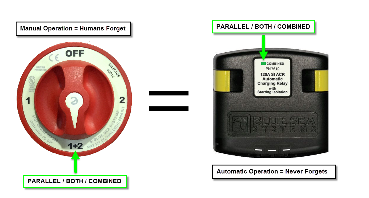
An ACR is nothing more than a fully automatic, voltage triggered, BOTH/PARALLEL switch that closes when charging voltage is present and opens when charge voltage is no longer present.
MHT RECOMMENDED PRODUCTS: AFILLIATE DISCLAIMER
BUY BLUE SEA PRODUCTS – AMAZON
You read that correctly, in its simplest form, all an ACR really does is parallel batteries when charging is present and un-parallel batteries when there is no charging present. It does this automatically with no human forgetfulness.
In days of old a boat owner had to use the battery switch to route/direct charging to the bank or banks they desired to charge. The most ubiquitous of these methods was simply switching to the BOTH/ALL or 1+2 setting on a 1/BOTH/2 battery switch. This was all well and good, charging in parallel, so long as the motor was running. However, when the owner stopped the boat the switch was often forgotten about and left in the PARALLEL position thus draining both batteries while on the hook.
Many a boater has succumbed to two dead banks due to what we refer to as HEF (Human Error Factor). Back in the early 90’s the first of the voltage sensing relays were hitting the market, thus no longer requiring the owner to do anything to the battery switch in order to charge both battery banks. Unlike a diode type isolator, which causes an approximate 0.6V volt drop to the batteries being charged, the combiner/VSR’s were simple voltage triggered paralleling switches and both batteries could be charged without human intervention or the voltage drop associated with diode type isolators.
The Blue Sea Systems ACR’s (automatic charging relays) are one of the most common charge management devices in existence today. In a conversation with Wayne K. of Blue Sea Systems, a number of years ago, he suggested that over 500,000 ACR’s had been sold world wide. Wayne has been retired now, for at least a few years, and that number is now likely much larger. Blue Sea Systems is not the only manufacturer of “Combiner/VSR’s” and today the competition is actually quite wide spread including; Yandina, Sterling Power, Victron, BEP and many, more. Even Smartgauge makes a VSR and the Balmar Duo Charge can be wired to work as a simple VSR. This article deals specifically with the Blue Sea Systems ACR, because they are easily the number one seller in this class of CMD’s. Most VSR’s operate similarly but with varying voltage triggers or delays.
Definitions used in this article:
Charge Management Devices (CMD’s): Devices used to route or direct charging sources to a targeted battery or battery bank. They include ACR/VSR/Combiners, DC to DC buck or boots chargers, diode type battery isolators, DC to DC buck type chargers & DC to DC current limited voltage following devices.
Automatic Charging Relay (ACR): A Blue Sea Systems trade name for an electronic voltage triggered paralleling relay
Voltage Sensing Relay (VSR): A generic term for an electronic voltage triggered paralleling relay
Combiner: Another generic term for an electronic voltage triggered paralleling relay
The term ACR is a trademarked term by Blue Sea Systems for their version of a VSR or voltage sensing relay. The class as a whole is know by many names such as VSR’s, ACR’s, Combiners, Parallel Combiners etc. and they all do just about the same thing.
Despite the gross simplicity of the Blue Sea Systems ACR these little units are fraught with myth and lore. Let’s take a look at some of the myth & lore that are often incorrectly assumed;
ACR Myth & Lore:
1- “An ACR charges the start battery first then isolates it and charges the house” = FALSE
2- “An ACR gives priority charging to the start battery” = FALSE
3- “An ACR will over charge a start battery” = FALSE
4- “An ACR can’t be used with mixed chemistries” = PARTIALLY FALSE
5- “You can’t charge the house bank first or the start battery will never get charged” = FALSE
6- “Blue Sea says to wire charging to the start battery only.” = FALSE
7- “With a smart battery charger you must wire an ACR disable switch into the negative lead of the ACR” = MOSTLY FALSE
8- “When the ACR combines batteries the massive in-rush current can blow up a battery.“ = FALSE
9- “An ACR will allow the start battery to drain into the house battery and leave it depleted.” = FALSE
There are many, many more but, you get the point. Hopefully this article can show you why the above myth & lore are just that.
What is a Relay?
A relay is the control device used inside a combiner, VSR or ACR. It is nothing more than an electronic switch that is closed or opened using a relay coil. By energizing or de-energizing the coil the relay can change positions from OPEN to CLOSED or CLOSED to OPEN.
In this image we are looking at the guts of a combiner/VSR that was 7 years old. It had somewhere around 12,000 hours of parallel combined use on a world cruising boat with solar, wind, alternator and genset charging. As can be seen the contacts are still in perfect condition even after 7 straight years of 24/7/365 world cruiser live-aboard life. Despite these units not being sealed to anywhere near the level of the Blue Sea Systems ACR, the Blue Sea Systems ACR’s are fully epoxy potted, this relay is in superb condition.
What about VSR/ACR/Combiner reliability?
As a class these devices are one of the most reliable devices we’ve seen in the marine market. In fact I can’t recall a single Blue Sea Systems ACR, that we’ve seen, actually fail. This particular VSR, a Yandina, carries an unconditional lifetime guarantee. You can’t guarantee a product like this for life if they are not reliable. We actually see more manually operated battery switches go bad than we do Combiner/VSR/ACR’s. Some ACR’s, such as the Blue Sea Systems 7622 ML-ACR can be used as a manually operated parallel battery switch and a fully automatic ACR.
Inside a VSR/Combiner:
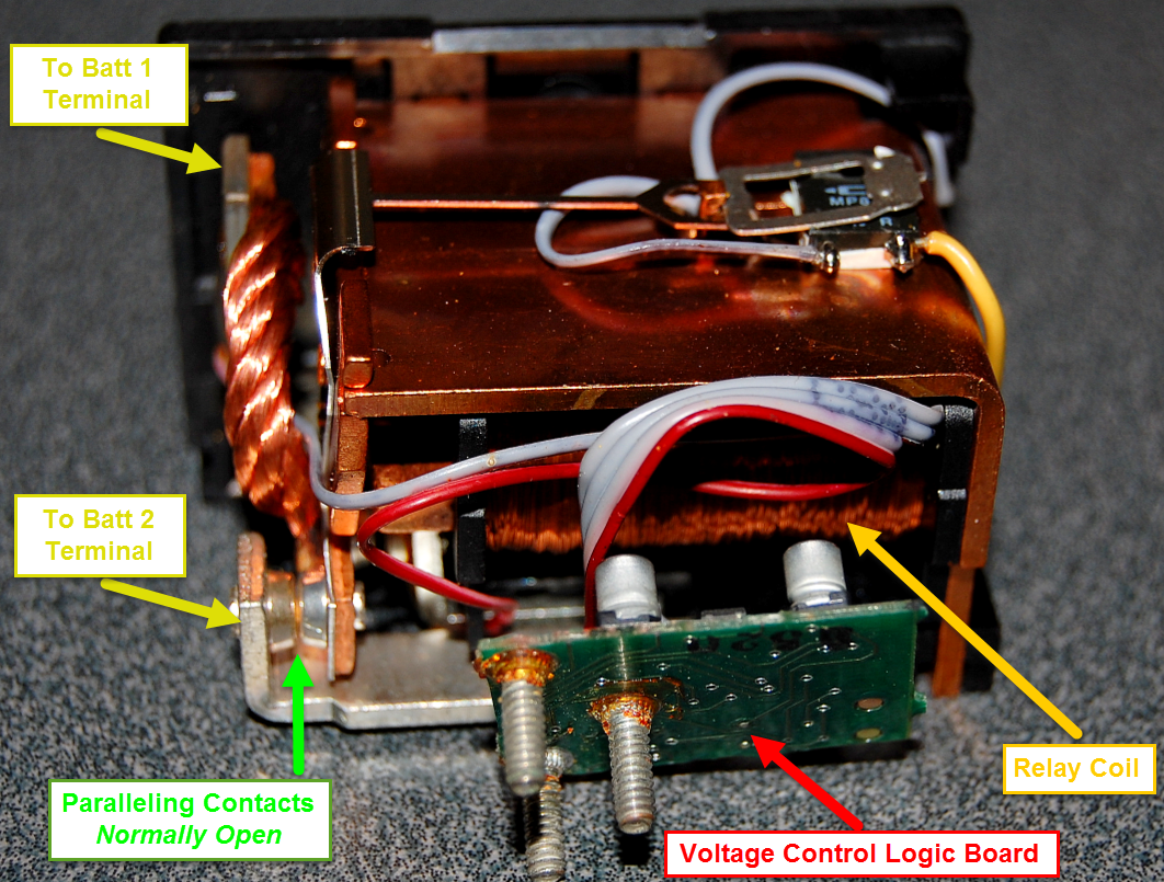
Contacts: We can see the natural state of the VSR and that is with the contacts normally open or what is referred to as “NO”. A relay with a natural resting state of closed would be called an “NC” relay. If a NO relay loses power it isolates or un-parallels the batteries. When the contacts are closed the batteries are in parallel.
Batt 1 & Batt 2: These heavy duty plated copper buses are directly connected to the Battery 1 and Battery 2 Terminals outside the unit.
Voltage Control Logic Board: This is the smarts of the combiner/VSR. This logic board simply measures the voltage at both Batt 1 and Batt 2 terminals and then tells the coil when to energize or de-energize to close or open the relay. Good quality combiners/VSR/ACR’s also have combine/un-combine delay logic and over or under voltage lockouts built in.
Relay Coil: The relay coil is what causes the contacts to move from open to closed or from closed to open. It is controlled by the logic board. Energizing this coil closed the relay and places the batteries in parallel. De-energizing the coil allows the relay to open and un-parallel the batteries.
ACR Parameters for Combine/Closed/Parallel
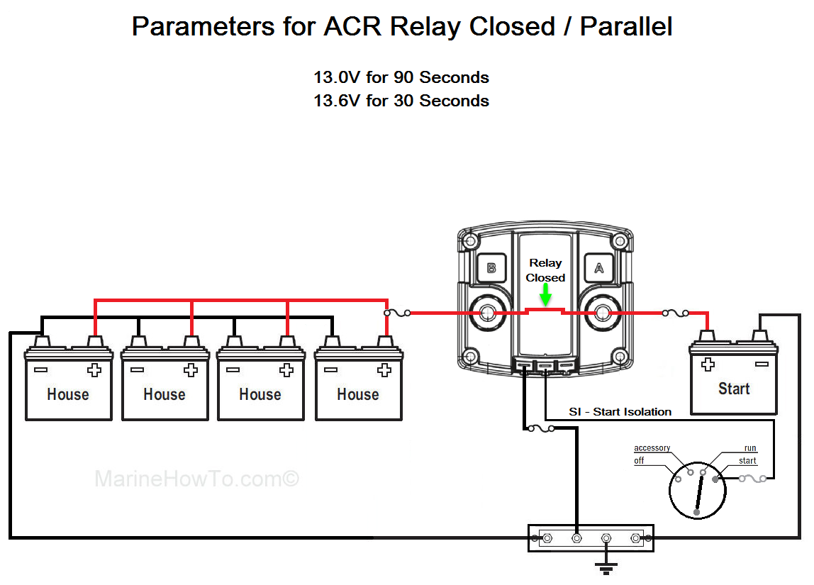
First we need to understand where to place/install an ACR. Placement matters. This image is intentionally over-simplified to show relay closed parameters and relay installation wiring and location. If you notice there are no battery switches, chargers, alternators etc. shown in this drawing. This is done purposely. Despite Blue Sea Systems heavily marketing their Add A Battery Kit (7650) an ACR or other combiner/VSR is completely independent of any battery switches. You do not need to purchase an additional battery switch to make an ACR work!
Where You Should Not Install an ACR:
An ACR does not get wired between battery chargers, solar, alternators, wind etc.. Don’t laugh, we have seen this done. As an example we had a customer wire the alternator output to one side of the ACR and the other side to the start battery and house battery with both house and start bank positive lugs stacked onto the “A” terminal. By placing the start and house battery positive wires on terminal “A” it meant the start and house banks were now hard wired in permanent parallel. This was oops #1.
For oops #2 the owner wound up blowing the diodes in his alternator twice before calling us. With the relay open the alternator output had nowhere to go and the voltage, almost instantaneously, surpassed the 16V over-voltage threshold and the ACR entered “over-voltage lock out“. With the ACR locked open alternator voltage kept climbing until the diodes in the alternator were blown. Bottom line? A Blue Sea Systems ACR is never installed directly into a charge devices positive output path.
Where You Should install an ACR:
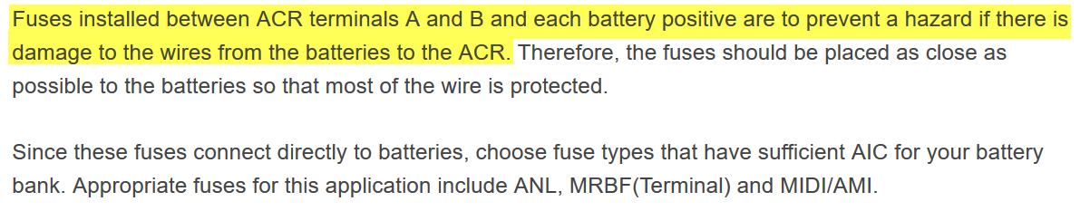
As can be seen in the image above an ACR is wired between the positive terminals of each battery bank with the only thing in its path being the fuses located within 7″ of each positive battery terminal. These fuses are there to protect the ACR positive wiring from the battery bank should they short to ground.
TECH TIP: If you make the “A” & “B” terminal wires for the ACR the same gauge as the house and start bank wiring eg: 2/0 and 2/0 the ACR can share the house and start bank fuses, if so equipped. Start banks are not required to have over-current protection but it never hurts.
The above image is how an ACR parallels:
13.0V for 90 Seconds: If either the B or A terminals of the ACR sense 13.0V for more than 90 seconds the ACR will close and parallel the batteries. The green arrow is pointing to the relay being closed and the banks are in parallel.
13.6V for 30 Seconds: If either the B or A terminals of the ACR sense 13.6V for more than 30 seconds the ACR will also close and parallel the batteries. The green arrow is pointing to the relay being closed and the banks are in parallel.
“I thought the ACR only sensed the start battery?”
Answer: The Blue Sea Systems ACR is a bi-sensing relay meaning it can sense/monitor charging or non-charging voltages at both the “A” & “B” terminals in order to parallel the banks or to un-parallel the banks.
ACR Parameters for Un-Combine/Open/Un-Parallel
Just like the logic used for closing the relay Blue Sea Systems also has logic to control when the relay opens.
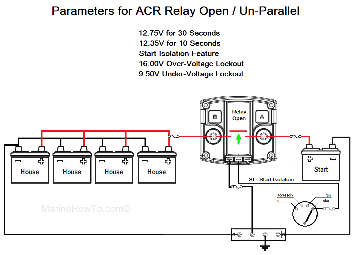
12.75V for 30 Seconds – If either the “A” or “B” terminal sense a voltage below 12.75V for more than 30 seconds the relay will open/un-parallel the batteries.
12.35V for 10 Seconds – If either the “A” or “B” terminal sense a voltage below 12.35V for more than 10 seconds the relay will open/un-parallel the batteries. IF voltage is trending upwards and attains 12.75V before 10 seconds has elapsed the relay will remain closed. This logic is here to enure a large load will not cause the relay to open when it creates a short duration voltage sag. It is also there to help minimize “relay cycling” which we will discuss later.
Start Isolation – The SI or “Start Isolation” feature is a unique to the Blue Sea Systems line of ACR’s. The start isolation feature momentarily opens or un-parallels both banks when the starter motor is engaged. The SI terminal of the ACR is wired to the momentary “start position” of the engine switch (see above image) or to the starter button. It is never wired to the “run” position. Doing this will keep the relay open indefinitely. Again, we’ve seen this done. When the starter motor is engaged the ACR’s relay opens so any voltage sag is not transferred to the house bank, where low voltage may cause electronics to shut down. For the SI feature to work as intended you need a dedicated starting battery and a dedicated house bank. The SI feature does not work with a 1/BOTH/2 switch where starting and house loads are shared by the same bank.
16.00V Over-Voltage Lockout – Over-voltage lockout is just what it implies. If the sensed voltage at either the “A” or “B” terminal is 16.00V or higher the ACR will lock out and open itself.
9.50V Under-Voltage Lockout – Under-voltage lockout is just what it implies. If the sensed voltage at either the “A” or “B” terminal is 9.50VV or lower the ACR will lock out and open itself. If you’ve drawn one battery too low don’t expect the ACR to combine until the battery gets back above 9.50V. In a case like this simply use your manual battery switch set to Both or your manual emergency parallel switch.
The above has covered myth & lore 1 & 2
#1 “An ACR charges the start battery first then isolates it and charges the house”.
As can be seen above the ACR does not in any way do this it is either in parallel or it is not in parallel. Very simple..
#2 “An ACR gives priority charging to the start battery”
Please understand that even if you feed charging to the start battery first, which is not advised on a cruising boat with disparately sized banks, 30 seconds of charging is not charging, even for a minimally depleted start battery. A battery at 99% SOC is in the worst range of charge efficiency. Despite being minimally depleted it still takes a good bit of time to reach an actual 100% SOC again. Each Ah we deliver to the battery, at a high SOC, is not being stored at 100% or even 50% due to the horrible Coulombic efficiencies at high SOC. The logic delays in the ACR are not there to create “priority charging” for a start battery or house battery they are there to eliminate relay-chatter and to help minimize relay-cycling or on/off/on/off/on/off behavior.
Q: “Why are there two different parallel voltages and delays?”
It is all about depth of discharge and when it is prudent to parallel the batteries. The lower combine voltage is there for a very good reason. It is there so that a deeply discharged bank does not take very long to attain the combine point. The higher combine voltage is there for a bank that’s not been deeply discharged and rises in voltage near instantly.
This all goes back to myth & lore #5 “You can’t charge the house bank first or the start battery will never get combined & charged”
Let’s put this myth & lore to bed…..
To address the question of the house bank taking a long time to combine with the start battery, we first need to consider a start batteries actual energy usage.
Start battery Energy Use?
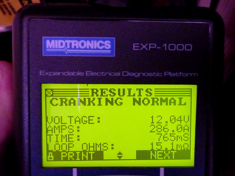
A battery used for starting an engine is using very little stored energy to do this job. It is a very short duration but also high amperage. Most engines will use considerably less than 0.5Ah to start. This is due to the cranking duration, loaded starter to unloaded starter, averaging 0.75 seconds to about 1.5 seconds (averages measured over 70+ marine diesel engines using the Midtronics EXP-1000HD). This means your previously full start battery will still be at about 99%+ SOC after you’ve started the engine. A 99% SOC battery does not really require immediate charging or priority charging and has many, many, many more starts left in it before any charging would even become necessary.
In the image above we have a 44HP diesels cranking diagnostics:
Averaged cranking voltage = 12.04V
Averaged cranking Amps = 286A
Loaded to Unloaded Cranking Duration = 0.765 Seconds
Even if we round up the cranking duration to 2 full seconds we are using just 0.17Ah. If we correct for Peukert, due to the high load on the battery, we are looking at a max fudge factor number of about 0.29Ah’s to start this engine.
Experimentation: For the sake of experimentation we cut power to an external voltage regulator then proceeded to start a Yanmar 4Jh forty-six times before finally getting bored. The battery used was a single Trojan SCS-200 Group 27 “Deep-Cycle” 12V battery. Not once did this group 27 “deep cycle” battery even so much as wince at starting this motor forty-six times, in less than one hour, without any charging what so ever.
The experiment above was only done to illustrate to an employee why we charge house bank first, not the other way around, on cruising boats. When you run the actual numbers, and see how little energy is used to actually start a motor, it becomes much clearer.
Q: “But how long does it take to attain a combine/parallel voltage?”
From 50% DOD/SOC, the max depth of discharge recommended by most lead acid battery manufacturers, it takes a bit less than 2 minutes at a .2C charge rate to attain 13.0V and this experiment was done on a high acceptance AGM battery.
Q: What is .2C?
The term .2C simply means 20% of the battery banks Ah capacity in charge current. Blue Sea Systems knows how simple it is to attain 13.0V, even for a deeply discharged bank, and this is why their ACR’s feature two differing combine/parallel voltage points, one at 13.0V & 90 seconds and one at 13.6V & 30 seconds.

This battery began charging at 50% DOD/SOC when the clock read 12:00. The charge rate was .2C or the bare minimum recommended charge current for this Lifeline AGM battery. As can be seen, after just 2 minutes of charging at 21A, it is already at 13.1V and the ACR can now combine. If your start battery is going to suffer not being charged for two +/- minutes, you have other issues.
Rumor/myth & lore #5 goes something like this: By using a battery combiner, on “high acceptance” AGM batteries, and feeding the alternator or battery chargers charging current directly to the house battery bank first, “it will leave your start battery under charged“ because “it will never get to the combine voltage or will take too long to get there”.
If you are practicing good battery management, and have even the minimum suggested charge current for an AGM or flooded battery, this is really a non-issue. In 2 minutes of charging, at .2C or 20% of Ah capacity from 50% SOC, the AGM battery voltage is already at the parallel/combine level for the Blue Sea Systems ACR. Even at .1C or 10% of Ah capacity the time to attain 13.0V is not very long, just a few minutes more. To get from 13.0V to 14.4V+ does take quite a bit more time but the relay has already combined at 13.0V and both banks are now being charged.
Battery voltage will rise pretty slowly from the low 13’s on but, to get to an ACR’s combine level, is relatively quick and easy, especially if you have your system set up properly. When hearing this rumor we need to also consider that Echo Chargers, Duo Chargers and a number of other DC to DC chargers also turn on at similar voltages and those devices require all charge sources to be fed directly to the house bank. On cruising boats with disparate sized banks Blue Sea Systems recommends feeding charge current to house first, not start, but you have the option to choose start first if you really feel the desire and you don’t with other products such as the Echo Charger, Digital Duo Charger etc….
Correctly Wiring an ACR on a Cruising Boat
While a three wire device, four if you use the SI feature or five if you use the remote LED indicator, seems simple to install, there are some areas that can trip you up. One of the most common blunders we see on cruising boats is leaving the alternator wired to charge the starting battery first. This is most often the result of the Blue Sea Systems instructions not being very clear. The majority of these are sold for use on boats where the battery banks are nearly identical in size. They are very, very popular on center-console and walk-around fishing boats where the start battery and house batter are nearly identical in size and the motor is started and stopped multiple times per day while fishing and owners don’t want the sounders and plotters to drop out during starting (SI). With both banks nearly the same size feeding the start battery first works pretty well. Because most builders sell boats wired this way, alternator feeding start battery, this is how they are typically wired. In an ideal world the charging would be fed directly to the bank that gets most depleted.
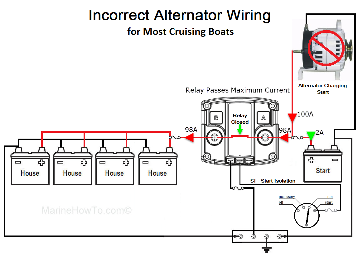
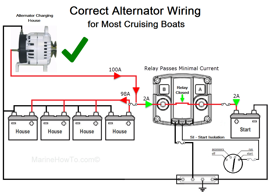
On a cruising boat, with a large house bank and small start or start/reserve bank, the best way to wire an ACR is to have the alternator charge the house bank directly.
“Why is it best to charge the house first?”
There are a number of reasons to do this but the best reason is to ensure the bank that needs the most charging is actually getting it and getting it as efficiently as possible.
#1 With large house banks wiring charging sources to the HOUSE bank means more efficient charging and more optimal voltage sensing for the alternator.
#2 With large house banks, wiring charging sources to the HOUSE bank means less chance of what is called relay-cycling. Please take the time to read the link below. Blue Sea Systems covers relay cycling very well so there is no sense in us repeating it.
Relay Cycling – Blue Sea Systems
#3 By wiring charge sources to the larger HOUSE bank the relay contacts need to pass just a few amps at best in order to charge the start battery. By feeding all charging to START means the relay must be able to handle the full rated current of the alternator and we are utilizing it at max duty cycle. We are also passing the charging current through multiple more terminations and fuses and there will be additional voltage drop.
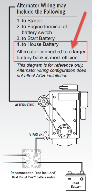
One part of the instructions that most installers miss is this:
What About Fusing / Over Current Protection?
One topic that comes up rather routinely is ACR fusing/over-current protection. Because the ACR or VSR is connected directly to the battery banks + terminals, or their respective *close-by charge / always on distribution bus, the wires themselves need over current protection. There is some confusion regarding ACR fusing, even among some professionals, that the fuse is intended to protect the ACR, and it is not. The fuse is there to protect the wire as Blue Sea Systems clearly illustrates below. If we are following ABYC standards these fuses should be within 7″ of the banks positive terminals or their bus.
(*Within 7" of the banks + terminal)
Fuse Sizing
One mistake we see all too often is a 120A 7610SI ACR installed with a 120A alternator feeding directly to a start battery and the relay is protected by a 120A fuse. If the house bank is heavily depleted the relay can conceivably pass close to 120A across it for a short period of time or until the alternator heats up and can no longer produce its cold rating. Also keep in mind that many alternators can exceed the cold rating for short periods by as much as 15%. I think you can see why a 120A alternator with a 120A fuse would spell disaster for the fuse especially when fed to the start bank first.
The fusing is there to protect the wire not the ACR, so if you have a 120A alternator the minimum fuse & wire size should be 175A & 1 AWG minimum. Fuses should not be run at 100% of their rating or they will eventually nuisance trip. This is why Blue Sea Systems calls for a 175A fuse for a 120SI ACR when being used with a 120A rated alternator. Of course if you wire it correctly, for a cruising boat, and the alternator feeds the house bank first, the relay will never see 120A across it except during very brief inrush duration’s that are not long enough in duration to trip the fuse.

TECH TIP:
If your house and start banks already have over current protection you can simply use the same size wire for ACR “A” and “B” terminals as the bank is wired with. In other-words you can share those fuses for protecting the A & B ACR wires, provided you use the same size wire. If both banks are already fuse protected this can mean no additional fusing costs for the ACR installation. If you make use of an already fused charge/always on bus, as shown below, you can just connect the ACR to that bus with the same size wire the banks are already using. In the example below the banks are wired with 2/0 wire and fused at 300A.
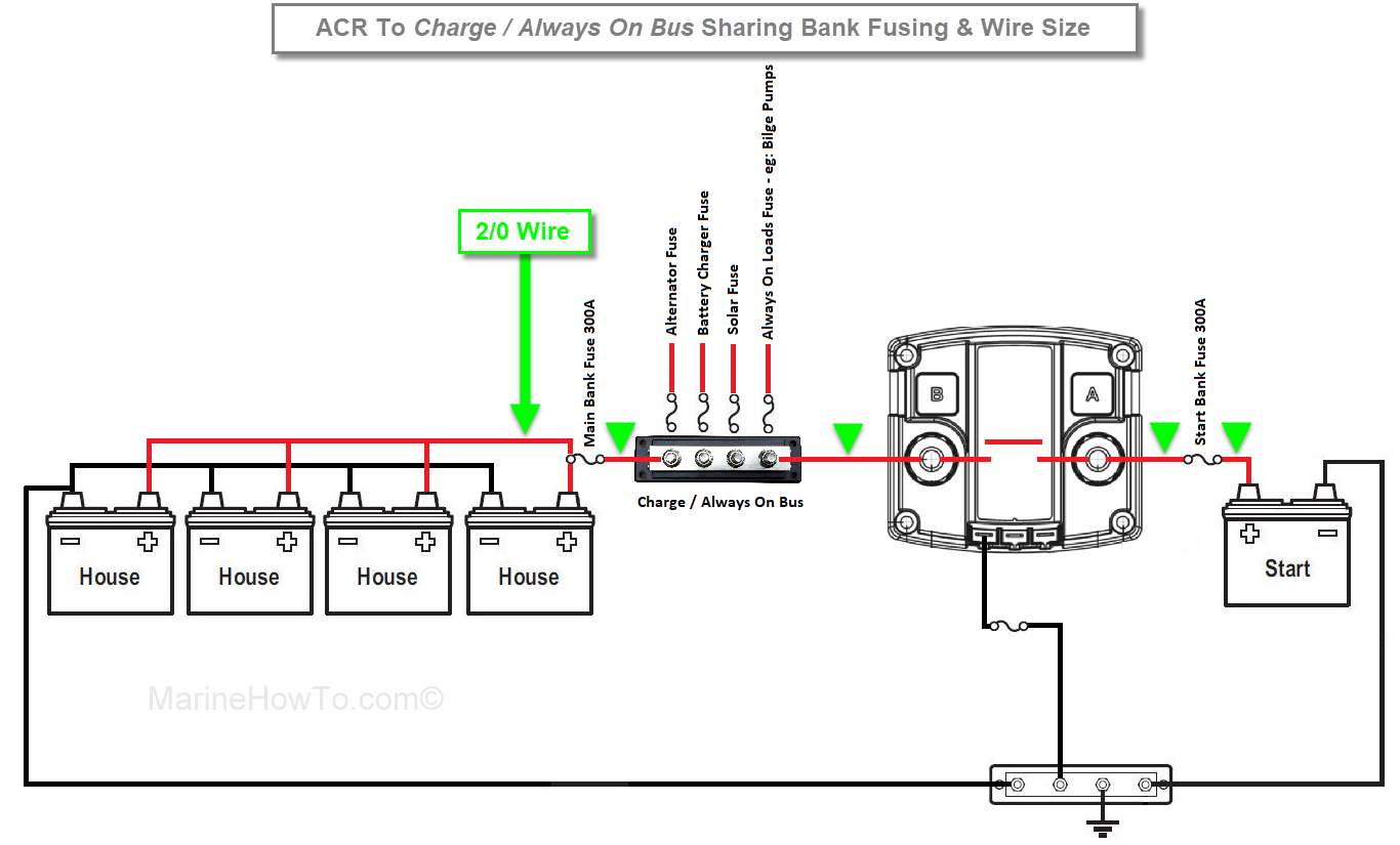
The use of a charge / always on bus is certainly a best practice and one more professionals and DIY’s should do more often. A charge/always on bus prevents messy bank wiring & incorrect lug stacking and makes for a neat and tidy installation anyone can easily troubleshoot.
Connecting Other Charging Sources
One of the major benefits of an ACR is that it works with any and ALL CHARGE SOURCES. Because an ACR is triggered by voltage changes it means that its an extremely valuable tool for charge management. Unlike a diode type isolator, that can really *only work with an alternator, the ACR can work with alternators, wind, solar, hydro, fuel cells, and AC chargers.
Diode Isolators;
Diode type isolators do not have a voltage reference on the input stud. By voltage reference I mean if you place your DVM on the input stud of a diode type isolator you will read 0V. This is one of the number one trouble shoot calls we get from folks trying to integrate solar or wind to multiple battery banks using a diode isolator. A diode isolator can’t be used with most charge sources that need to see a DC voltage before booting up. Today most voltage regulation charge sources have a feature that does not allow them to boot into no voltage where a typical “dumb alternator regulator” will. This is a safety feature so you’re not charging into a failed battery. Today there are very few good uses on a boat for a diode type isolator.
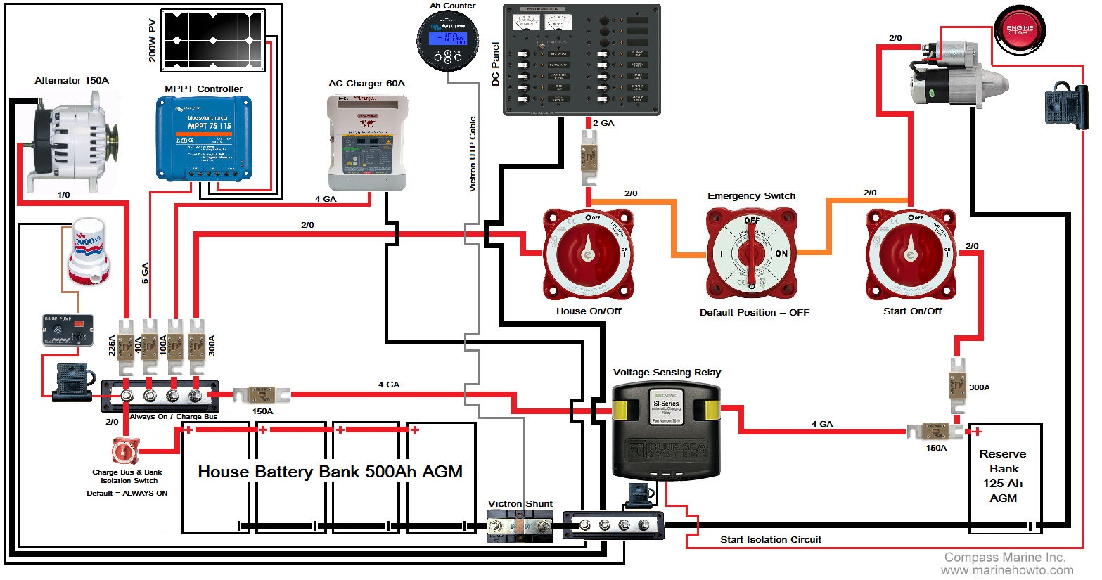
The question of other charge sources ,and an ACR, comes up a lot. Due to marketing it can be a bit murky wading through it all. The bottom line, for simplicity & operational sake on a cruising boat, is that you want to wire all your charging sources to the largest bank eg: the house bank. This would include, alternator, AC powered battery chargers, inverter/chargers, solar, wind, hydro or fuel cells. It is critically important to wire low-current charge sources such as solar, wind, hydro, fuel cells or small battery chargers directly to the house bank to prevent relay cycling.
In the image below we can see a cruising boats foundation wiring with a 500Ah AGM HOUSE bank and a 125Ah AGM START/RESERVE bank. As can be seen all charge sources feed the house bank and the ACR parallels in the start bank when 13.0V or 13.6V is attained.
What about twin engine boats?
On twin engine boats one alternator, usually the largest and most capable, can feed the house bank directly and one can directly feed the start bank directly. The addition of an ACR means that both alternators will contribute to the house bank charging during bulk. Without the ACR the start bank alternators full capability is just being wasted by feeding a few amps at best to the start battery. By adding an ACR we can make much more effective use of both alternators and charge the house bank faster.
Myth & Lore #10;
“With a smart battery charger you must wire an ACR disable switch into the negative lead of the ACR”
This one can be a bit confusing but all boils down to what is actually inside a “smart-charger“. If your smart charger actually has multiple voltage regulators and multiple power supplies inside it, then a switch in the negative lead can allow the charger to charge each bank with its own fully independent charge profile. The catch here, and why this is MOSTLY FALSE, is because finding a smart charger with two or three fully independent chargers inside one box is about as likely as Hillary Clinton switching parties and becoming a Republican. Follow me for a moment..
What you think you’ve paid for:
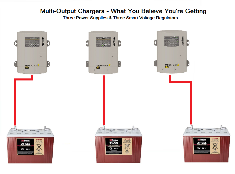
What you actually have:
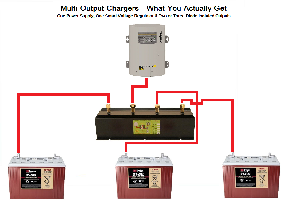
Another way to view most multi-output chargers would be like this:

With this image it becomes more clear how the single voltage regulation and single power supply can be connected to multiple batteries through “isolated outputs”. For this example I drew simple diodes, an electrical one-way check valve, but most chargers these days are using FET’s on the outputs to achieve the same effect. The only purpose of the FET or diodes on each output leg of the charger is to prevent the batteries from back-draining (in parallel with each other) into each other when the charger is turned off. You guessed it all batteries get the exact same charge profile just as they would if you fed charger output #1 to HOUSE and then used an ACR to charge the START battery.
Let’s discuss myth & lore #3: “An ACR will over-charge a start battery”
Please examine the above images and let them hit home. Now ask your self a simple question; How is a “smart charger”, a model that uses one voltage regulator and one power supply and two or three diode or Mosfet (FET) isolated outputs, any different than the BOTH setting on your battery switch or the combined mode of an ACR? If you landed on “its not any different” reach over your shoulder and pat yourself on the back. The diodes or FET’s on the single circuit of a multi-output charger are only there to prevent parallel back-drain when the charger is turned off. An ACR achieves the same exact outcome, preventing back-drain, by opening the relay when no charging is present.
The same guys who walk the docks and profess that an ACR will over-charge a start battery are quite often the same guys professing why you need a smart charger to charge your multiple on-board battery banks. I know this because one of these guys attempted to re–edumacate me on a dock one day, & he used this very argument. The charger on his own boats was a muti-output single power supply single voltage regulation unit. The funny part about this re-edumacation was the start battery on the boat I was working on was 8 years old and had been charged via a Blue Sea Systems ACR for the entire 8 years. It had been charged via multiple charge sources, including a shore charger, solar & alternator. According to the “dockspert” that start battery had been murdered 7 years ago by the ACR yet in the real world it was still going strong at year 8.
It was not worth trying to explain the concept to him, in a short period of time, and besides he’d already made up his mind on the subject. Little do folks realize there is usually no difference between using the multiple-outputs of a battery charger vs. using just one output of the charger and an ACR.. The ACR simply prevents back-drain by opening the relay when there is no charging & the smart charger uses diodes or FET’s to prevent back-drain. Whether you use the isolated outputs of the charger or one leg of it, and an ACR, there is really no difference.
The vast majority of multi-output smart chargers are one charger hiding behind two or three back-feed prevented (diodes or FET) outputs. If you want to charge multiple banks, and you already have an ACR, use the ACR, as it will work with all charge sources. This will save you charger to bank wiring and an extra fuse/s. To get around the multi-output charger and differing bank voltage profile conundrum, a situation where neither the multi-output charger nor the ACR would be a good choice, Sterling Power products offers their Battery Chemistry Module.
Ok back to our dockspert for a moment.
If your single power supply, single voltage regulation smart-charger is not over-charging your start battery, how is it that an ACR would?
Think about it…… Even Blue Sea Systems own “P-Series” chargers are one single voltage regulator and one single power supply. They market the product describing how it can float one bank while charging the other at absorption. While this is certainly a nice selling feature we still have millions of single VR/single power supply multi-output “smart chargers” out there that don’t do this, and yet we don’t have start batteries being routinely over-charged & murdered.
What Blue Sea Systems is actually doing in the P-Series is switching in an additional diode to the start battery output leg. Switching in an extra diode causes a 0.6V drop on the start battery output. It is not a truly independent smart charge profile but rather a 0.6V drop from the absorption voltage & a nice selling feature for sure. To do truly smart-charging, the type most boat owners assume they have, the charger would need multiple voltage regulators and multiple power supplies something very, very few chargers actually have.
Still, if you desire to allow your “smart-charger” to do it’s thing, or you use a Sterling Power Battery Chemistry Module or Blue Sea “P-Series” and feel it does a better job than the ACR, by all means insert a simple ON/OFF switch into the negative lead of the ACR, to disable it, or just flip the switch of the ML-ACR to OFF..
When to Use a VSR/ACR/Combiner
To keep this simple, when charging lead acid batteries, is that it’s all about the appropriate charging voltages. Also we can’t forget that GEL, AGM, TPPL AGM and Flooded Deep Cycle batteries are all lead acid chemistry.
With that in mind;
If both banks can be charged within 0.1V to 0.2V of each other, an ACR is a fine choice
Same Chemistry & Same Charging Voltages = √
Same Chemistry & Very Similar Charge Voltages = √
*Mixed Chemistry & Same Charging Voltages = √
*Mixed Chemistry & Very Similar Charge Voltages = √
*Excludes mixing lead acid and Li-Ion batteries
Most lead acid batteries will have a safe voltage range for absorption & float. If we compare a bank of Trojan golf car batteries and a Trojan Group 31 12V battery it’s clear to see they share the same charging voltage range and thus a VSR/ACR/Combiner is a good chocie for this application.
When Not to Use a VSR/ACR/Combiner
If we go back to Myth & Lore #4; “An ACR can’t be used with mixed chemistries”
We describe this as “partially false” and here’s why…
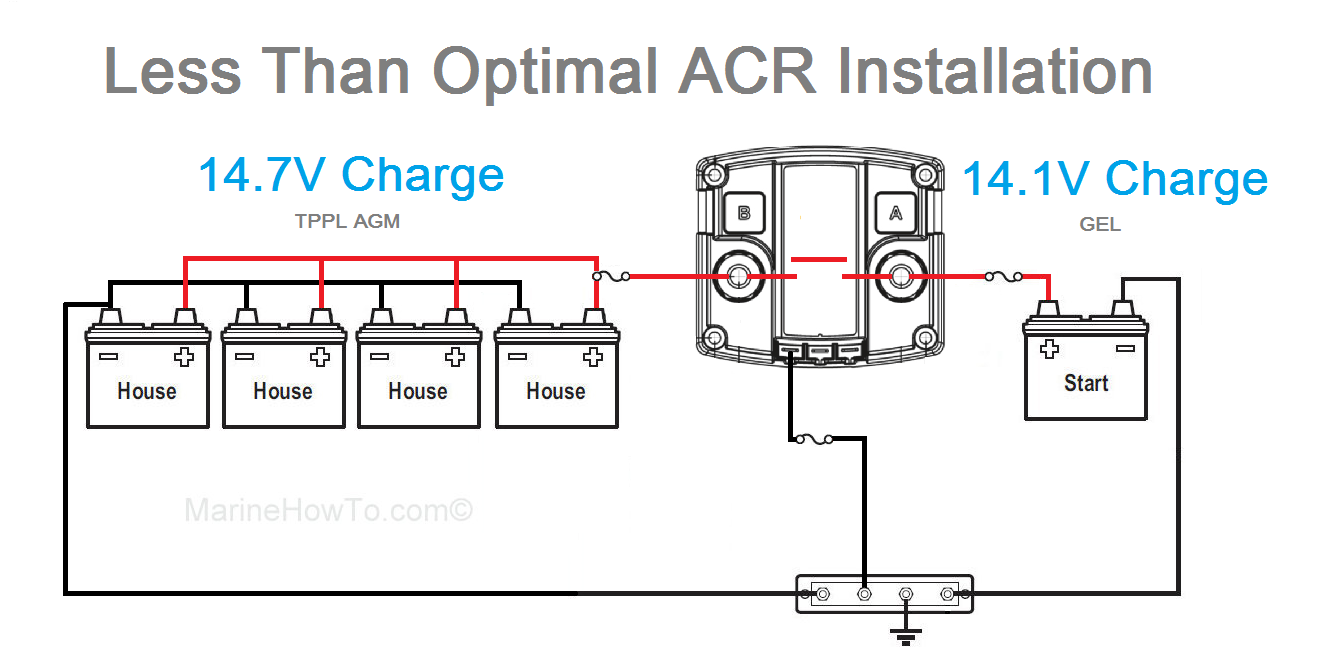
Let’s assume you have a GEL house bank, an excellent deep cycling battery, and a TPPL AGM windlass bank and excellent high current capable windlass or thruster bank. The GEL battery should not be charged at over 14.1V to 14.2V so the primary charging sources, solar, wind, alternator, chargers etc., would all be set up for a maximum of 14.1V to 14.2V. The problem here is that the ideal charging voltage for a TPPL AGM bank is closer to 14.7V. In this case, if charging is set up for 14.1V to 14.2V, we will wind up chronically undercharging the TPPL AGM bank via the ACR.
If we reverse this scenario, and the charging is tailored to the TPPL AGM bank, we will quickly destroy the gel battery by over-charging it.
Same Chemistry & *Differing Charging Voltages = X
Mixed Chemistry & *Differing Charging Voltages = X
*Differing by more than 0.3V
If specified charging voltages are the same or similar then an ACR/VSR/Combiner is a worthy choice. Once we get beyond about a 0.3V difference, it starts to make more sense to move to a DC to DC charger such as a Sterling Power Battery to Battery Charger where we can get a true fully independent smart charge profile.
“But an ACR will Discharge my Start Bank.”
This statement takes us directly to Myth & Lore #9 “An ACR will allow the start battery to drain into the house battery and leave it depleted.”
The fully charged resting voltage of a typical lead acid battery is about 12.72V. At any voltage above this point there is really no usable energy stored when discharging (see image below).
By now I know you are understanding it, but if not, this one is really quite simple. The ACR normally opens/un-parallels at just above or just at the 100% SOC point of a lead acid battery. If either battery bank dips below 12.8V the relay opens within 30 seconds. If it dips to 12.35V, the relay opens in just 10 seconds. The answer to this myth is that it is indeed false that an ACR will allow the start battery to discharge into the house bank. Your start battery cannot discharge into your house bank in 10 or 30 seconds.
The discharge graph below (voltage is the red line) was a typical marine battery undergoing a 20 hour capacity test. The battery was fully charged, equalized and had an open circuit voltage before the discharge test of 12.95V or what we refer to as a “surface charge“, despite having rested for a full 24 hours prior to the test. Because this was a 130Ah rated battery the discharge rate was 6.50A (130Ah / 20 hours = 6.5A discharge rate). At data point #1 the battery was at 12.95V and by data point 2 the battery was already below the open/isolated/un-parallel voltage of the ACR at 12.76V.

You are seeing that correctly, by the time this battery hit 12.76V a paltry 0.002Ah worth of energy had been removed. If the ACR opens at 12.8V how much can we discharge either bank by? This answer is nothing worth even really discussing…
If the relay opens at 12.8V it can’t remove any Ah quantifiable capacity from either bank before the banks are isolated.
This does bring us to another myth we have heard and that is when the banks are combined, in parallel, they can transfer energy between each other. This one is also a pretty simple explanation.
The ACR combines at well above the natural resting voltage of a lead acid battery. Due to this, charge current can only flow in one direction and that is into the battery. At 13.0V or higher current flows is into the battery from the charge source and the charge source would take up both the DC loads and the charging.
The combine point of 13.0V is a charging voltage and when a battery is charging it can not also be discharging. It can only be discharging when voltage is below charging level. Very, very simple.
The final point we should discuss is myth & lore #8;
“When an ACR combines the massive in-rush current can blow up a battery.”
The easiest way to answer this question was to create a scenario on the test bench that could show these “massive” currents, currents so huge they can blow up a battery. (sigh)
The math could easily be calculated to show why this is not a concern but, it is often easiest to physically see it in action. In the video below we created and tested for the scenario that created the highest in-rush current we could create. The term in-rush, as related to this example, just means the absolute peak current measured over a very *brief time period, between banks, at the widest voltage spread.
*The Fluke 376 captures current transients at 0.1 second or one tenth of one second.
The point where the banks are combined, and voltage spread is widest, is the point where the most current transfer is created. This in-rush lasts less than .2 seconds and current transfer, between banks, literally nose dives very rapidly as the bank voltages close in on each other and attain parity.
We created this scenario based on a very popular 315Ah AGM house bank (3 G-31’s) with an AGM starting battery. In order to try and capture the most in-rush we could, an Odyssey Thin Plate Pure Lead AGM, or TPPL AGM, was chosen as the start battery. The Odyssey PC2150M is a battery that can deliver over 5000A of current into a dead short, 2150A of cranking current at 77F and 1150A of cranking current at 0F. The 172A peak current it delivered to the house bank, for about .2 seconds, is literal child’s play. The test delivered the maximum recorded in-rush current at about 30% state of charge or a 70% depth of discharge. This is a depth of discharge you should not be routinely seeing with typical AGM batteries. Interestingly enough when we discharged the large house bank to 80% or 90% DOD the maximum in-rush was actually lower than it was at about 70% DOD. We chose to show the maximum in-rush we could create.
If we have 315Ah’s of AGM batteries, and we play pretend fairy-tale stories and assume the 172A in-rush could last for even 30 seconds (it can’t physically do this) this equals a charge rate of about 0.54C or just 54% of Ah capacity. In the Practical Sailor PSOC testing all the AGM batteries were actually charged, not an in-rush, at .46C (46% of Ah capacity) and the batteries barely even got warm to the touch. Of course this extremely short in-rush is not a “charging current” it’s a fraction of a second peak-transient current and is in no way dangerous to your battery bank. Yes, myth & lore #8 is indeed false and there are no “dangerous” in-rush currents created when the banks parallel with each other.
Another example of why this is not dangerous, Lifeline battery states their 100A AGM battery can handle 500A of in-rush charge current with ease. This equates to a charge rate of 5C or 5 times Ah capacity. As you’ll see below the ACR switching closed could only transfer 54% of Ah capacity in this test for a very brief 0.2 second transient.
In this video you will also see the effects of relay cycling and why hooking up a cruising bank incorrectly can create this phenomenon..
Choosing an ACR
Blue Sea Systems offers two distinct types of ACR models, the basic fully automated SI-ACR’s and the larger, manual or fully automated ML-ACR’s. Both charging relays feature fully potted electronics, heavy duty 3/8″ studs and the ability to charge two banks.
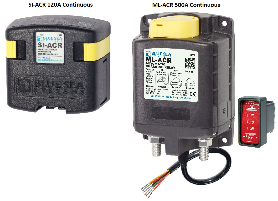
ML-ACR – The ML-ACR is a step up from the basic SI-ACR, and also costs a bit more. For a bit more money you get a lot more in features and current carrying capability and it can handle as much as 500A continuously. The ML-ACR also allows for manual paralleling of banks via a dash mounted toggle switch or the yellow knob on top of the ML-ACR. This means the ML-ACR could take the place of your emergency paralleling battery switch and do double duty as both an ACR and an emergency paralleling switch. The 500A continuous rating makes it the ideal product for boosting the available current to a bow bank used for a windlass or a bow thruster. With the flip of the toggle switch it can go from automated ACR charging, which would open on voltage sag, to manually locked in parallel. This means your bow bank, house bank & alternator can now all contribute to your windlass or bow thruster performance and you can rather drastically improve bow thruster or windlass performance. The ML-ACR also features SI or start isolation. Standby draw on the ML-ACR is a scant 13mA or just 0.013A.
SI-ACR – This is the basic fully automated model and is a relatively inexpensive upgrade. The 7610 SI-ACR can handle 120A continuously, has SI (start isolation), fully potted electronics and heavy duty 3/8″ studs. If you don’t need the high amperage or manual paralleling feature of the ML-ACR the SI-ACR is a great value. Standby draw on the SI-ACR is just 15mA or 0.015A.
Today there are lots of options for charging multiple banks, without suffering from voltage drop, and the Blue Sea Systems ACR’s are a great affordable option option. The Link below is to the MHT store on Amazon:Affiliate Disclaimer
Good luck with your project & happy boating!
Emergency!
We do not want to put this website behind a pay-wall!
Please make a donation, that’s all we ask. Your donations & affiliate purchases are all we have to fund this web site. Please help to keep MarineHowTo.com a FREE source of information!
 .!
.!