Lead is Dead! (Except for Starting Batteries)
Warning: This article is long and detailed—it may require two reads to fully grasp the nuances and important details.
You might be wondering why I’m declaring that lead is dead. The answer is simple: lead-acid battery manufacturers have dug their own graves by repeatedly misleading the public. They know full well that their batteries will never meet the cycle-life claims once they’re deployed in the real world—where partial state of charge (PSoC) operation is the norm.
Why not? Because the real world isn’t a pristine, white-lab-coat, white-glove laboratory. In the real world, sulfation happens—and it kills lead-acid batteries far earlier than advertised.
Not long ago, I was on the phone with the top-selling lead-acid battery vendor on Amazon. They recently began offering LiFePO₄ batteries after noticing a slump in deep-cycle lead-acid sales. Since introducing LiFePO₄, their LFP sales now outpace lead-acid roughly 2 to 1.
Cycle-Life Claims vs. Reality
Claims of 1,000, 1,200, or even 1,600 cycles are about as believable as Jim Gaffigan beating Usain Bolt in the 100-meter dash. In a sailboatowners.com battery usage survey—the largest of its kind, with 1,480 users responding—the overwhelming majority of boat owners reported getting maybe 150 cycles out of their lead-acid batteries. That’s 150 cycles! Many of these batteries were sold with claims of 1,000+ cycle life. It’s laughable.
Lead is dead—and the manufacturers have no one to blame but themselves. By grossly misleading their customers about realistic cycle-life expectations, they’ve essentially pushed users straight into the arms of LiFePO₄. Had they been more transparent, the mass migration to lithium might not have been so aggressive.
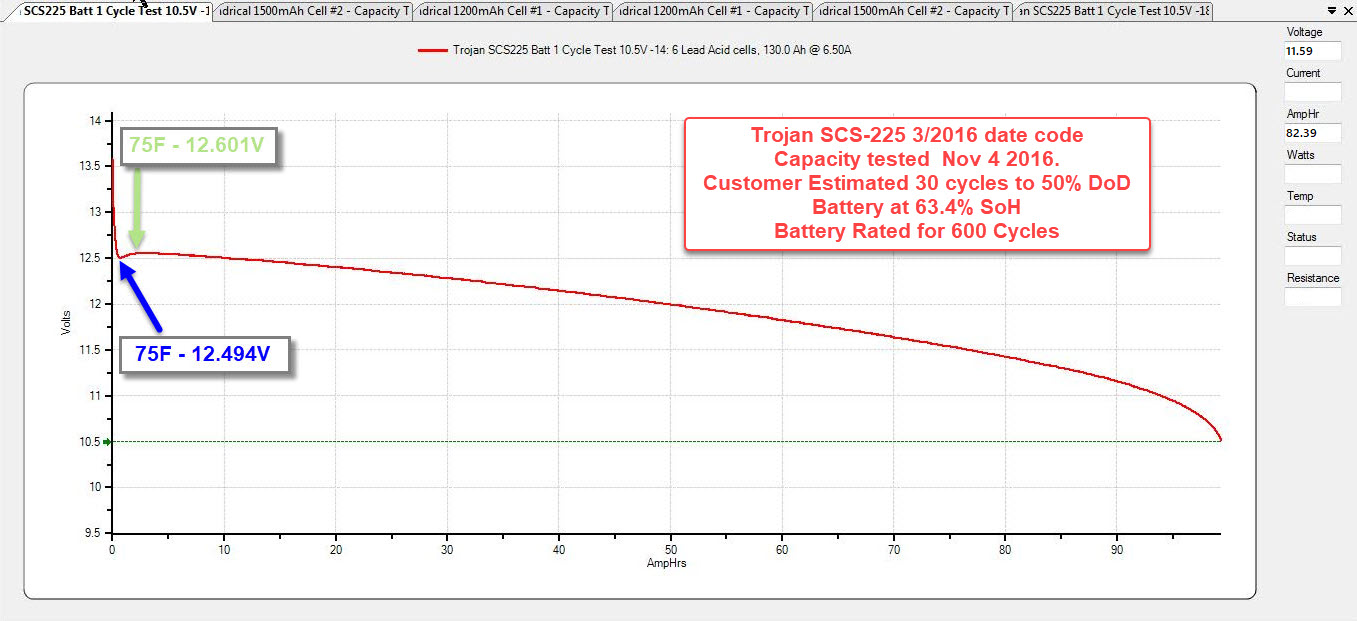
The image below is just one example of why I call lead-acid cycle-life claims a joke. I never make a claim like this without hard data to back it up.
Capacity Testing = Lead-Acid Reality
At Compass Marine Inc., we’ve been capacity testing lead-acid batteries for more than 20 years. While the test equipment has gotten better over time, sadly, the quality of the batteries hasn’t.
One unfortunate example: A customer purchased a brand-new bank of Trojan SCS-225’s in the spring. His boat was on a mooring, and he had no solar. I warned him those batteries might only last one to two seasons, but he was optimistic—after all, Trojan claims up to 600 cycles at 50% depth of discharge.
Reality? After just one season, the bank tested at 63.4% state of health. That’s nowhere near acceptable.
By industry standards, a lead-acid battery is considered end-of-life when it drops below 80% of its rated capacity. After two decades of testing batteries under BCI protocols, one thing is clear: claims of 1,000+ cycles for lead-acid batteries are pure fiction—right up there with Tinker Bell.
Cost: LFP Wins!
Let’s take a look at some real-world pricing as of 6/18/25:
Lifeline G-31XT AGM (125Ah x 3 = 375Ah bank)
-
Cost: $1,797
-
Usable Capacity: 187.5Ah (at 50% DoD)
-
Real World Cycle Life: ~300 cycles
-
Cost per Usable Ah Over Life: $5.99
(Based on 20+ years of real-world experience and many many hundreds of capacity tests)
WattCycle 314Ah LiFePO₄ (80%DoD)
-
Cost: $529.99
-
Usable Capacity: 251.2Ah (at 80% DoD)
-
Estimated Life: ~4,000+ cycles
-
Cost per Usable Ah Over Life: $0.13
Wattcycle 314n Ah LiFePO₄ (100% DoD)
-
Cost: $529.99
-
Usable Capacity: 314Ah (at 100% DoD)
-
Cycle Life: 2,000 cycles
-
Cost per Usable Ah Over Life: $0.26
Bottom Line
Even when used at 100% depth of discharge, lithium iron phosphate (LFP) batteries offer a tiny fraction of the cost per amp-hour compared to AGM. The economics speak for themselves—LFP isn’t just better performance, it’s better value.
Preface
This article covers 12V (nominal) LiFePO₄ “drop-in” batteries for use aboard boats.
It’s also the first article I’ve written since suffering a major stroke on September 1, 2021—a stroke that actually killed me but I was rescucitated. Recovery has taken over11 months, and while progress is slow, I’m grateful to be here and writing again with 1 finger.
Due to the stroke, I now use speech-to-text software (Dragon) to write. It’s not easy to master, and I only have one working hand—my right. My left arm and hand remain paralyzed. My vision was also affected, which means I can only work at the computer for 30–40 minutes at a time before fatigue sets in. That said, I’m building endurance slowly, and making progress every day.
This article has taken me over 120 hours to produce. Everything takes longer now—but I remain committed to MarineHowTo.com, and this article marks the beginning of my comeback. I had started outlining it in August 2021, just before my stroke.
Bare Minimum Features for Drop-In Batteries
If you’re considering a drop-in LiFePO₄ battery, make sure it has at least the following features:
-
Low-Temperature Charging Cutoff
-
Detailed Owner’s Manual
-
Compliance with ABYC Standards
-
UL Certification
-
Bluetooth BMS (critical)
Our Recommended Value Drop-In Battery: WattCycle
Right now, our top pick is WattCycle.
These batteries are impressively well-built. WattCycle offers:
-
Optional Bluetooth BMS
-
Waterproof models
-
Proper cell compression
-
Incredible value
Currently, WattCycle is the best overall value when factoring in construction, features, and price.We have Secured an 8% discount on top of the already amazing pricing. The coupon code is: MHT8.
Buy Discounted Wattcycle Batteries
Current LFP Pricing
Thanks to oversupply in the EV market, LiFePO₄ cell prices are still low—but this won’t last forever. I n a three year period LFP cell prices have dropped by 90%. Why? China spent billions scaling up EV battery production, only to see demand fall short. This has left cell manufacturers like EVE, CATL, REPT, Top Band, etc. with surplus inventory & production.
As a result, drop-in battery builders are now getting high-grade EV cells at prices well below production cost—something nearly impossible just two years ago. Companies like WattCycle are passing those savings on to the end user.
Even better: we’ve negotiated an 8% discount for MarineHowTo.com readers.
Use coupon code: MHT8 when purchasing via the link below to get 8% off + free shipping.
(Note: This code does not work on Amazon.)
Best for Victron Integration = Epoch Batteries
If you need drop-in batteries that communicate with Victron equipment, our recommendation is Epoch.
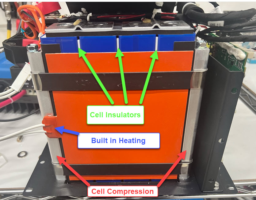
Epoch batteries are built to an exceptionally high standard:
-
Built-in heating
-
One of the best Bluetooth BMS units we’ve seen
-
Waterproof designs
-
CANBUS support
-
Remote display & alarm options
-
Proper cell compression
-
An in-house engineered BMS
Epoch batteries are manufactured by one of the top battery factories in China, a division of EVE, one of the world’s largest and most respected LiFePO₄ cell makers. This ensures excellent consistency and access to EV-grade cells.
Buy Discounted Epoch Batteries
Join the Discussion
Want to learn more or share your experience? Join our growing communities:
Yes, I Personally Use LiFePo4
Just so you know—I’m not new to lithium-ion batteries.
I’ve been using LiFePO₄ batteries on my own boat since early 2010. I built my bank in 2009, before any drop-in batteries even existed. As of May 10, 2023, the bank turned 15 years old, with over 2,500 cycles, most of them at 80% depth of discharge. Over 100 cycles went all the way to 0%.
Despite all that use, the bank can still deliver 100% of its original 400Ah rated capacity.
Yes—LiFePO₄ batteries can last. Lead-acid simply doesn’t compare.
Happy 15th Birthday to My LiFePo4
Summary of ABYC LFP Safety Testing
ABYC LiFePo4 Safety Testing Article
Here’s the FAA
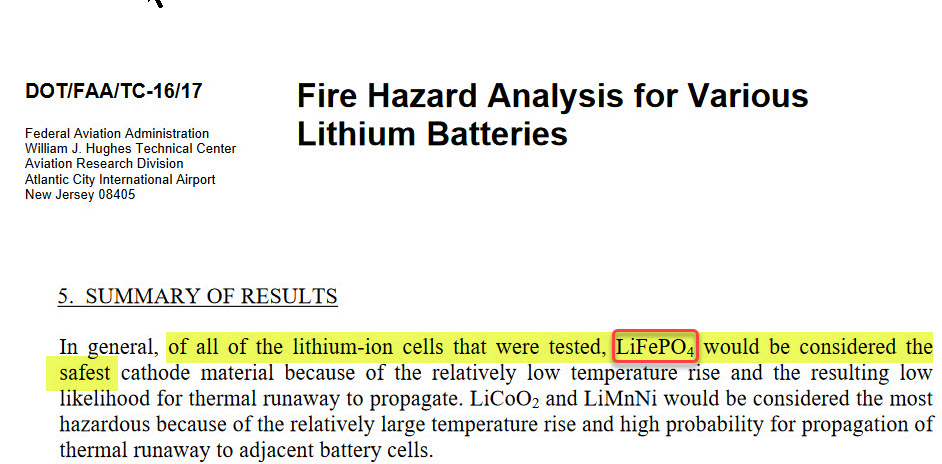
Dramatic example of LiFepo4 Safety
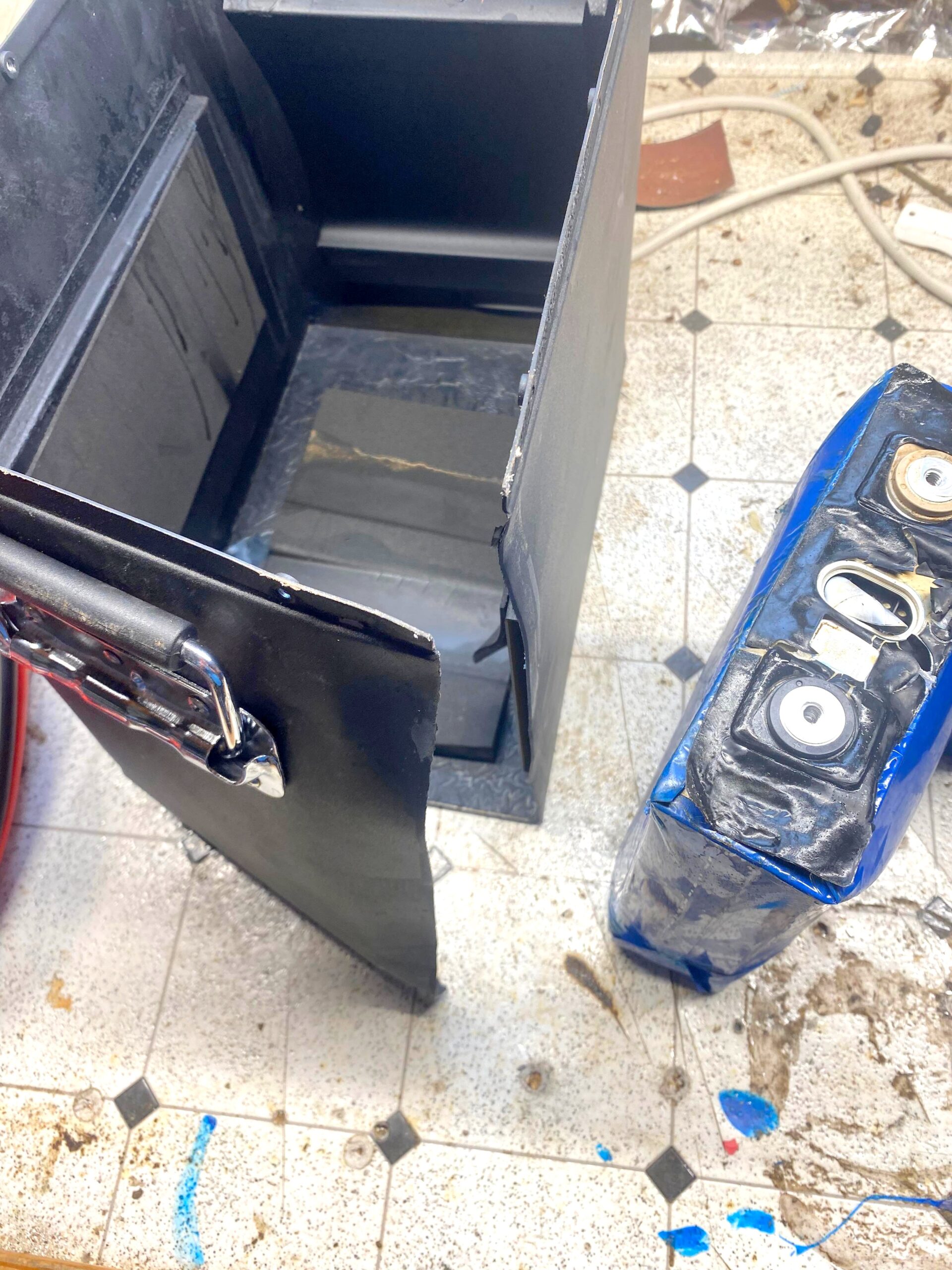
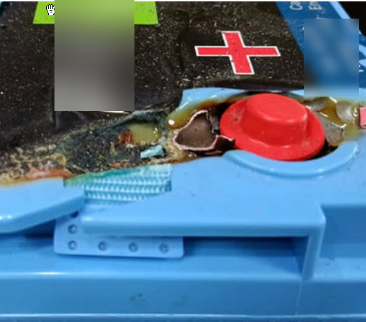
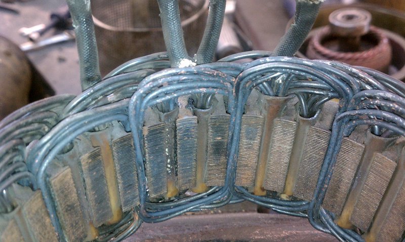
The image below is but one example of the safety of lithium iron phosphate batteries. The cells below came out of a drop in battery where the solar controller failed & the 100V+/- array started feeding hundred+/- volts to the batteries. The BMS tried to protect the batteries but once the BMS shut off. in the solar array was still feeding 100V+/- to the chip in the BMS. Once the chip failed the 100V made it to the FET’s and they too failed allowing the full array voltage to get to the LFP Cells. You can read more about this incident in the July issue of Professional Boatbuilder magazine
No fire, no explosion just swollen ruined cells & cell venting.
You can read about this failure here:
Professional Boatbuilder Article Link
Important Note
This article is not intended to criticize or single out any specific manufacturer. Its sole purpose is to help you become a more informed and educated buyer. Where possible, brand names have been intentionally omitted. I do call out one manufacturer by name, but that’s rare for me—and only done when truly necessary.
Don’t You Just “Drop Them In”?
No, you don’t.
Installing LiFePO₄ batteries on a cruising boat is not a plug-and-play upgrade. It requires a system-wide approach—just like converting from flooded to AGM or GEL batteries. Treat it as a complete electrical system consideration, not just a battery swap.
Terminology Used in This Article
-
LiFePO₄ = Lithium Iron Phosphate (also referred to as LiFe or LFP)
-
BMS = Battery Management System
-
C-Rate = Charge/discharge rate based on battery capacity
-
Example: A 100Ah battery at 0.5C = 50A (100Ah × 0.5 = 50A)
-
-
Load Dump = A BMS-triggered disconnect that cuts the battery off during charging
-
VPC = Volts Per Cell
-
Pack Voltage = Total battery voltage measured across the positive and negative terminals
What Is a “Drop-In” Battery?
A drop-in LiFePO₄ battery is a self-contained unit designed to fit in a standard lead-acid battery footprint—such as Group 24, 27, 31, 4D, or 8D. That’s where the term “drop-in” comes from: it physically drops into the same location as a lead-acid battery.
These batteries always include a built-in BMS. If a battery requires an external BMS—like those used with Victron, Mastervolt, or Lithionics systems—it’s not considered a drop-in battery.
Safety: Let’s Cut the BS
Let’s be crystal clear: LiFePO₄ and LiCoO₂ (the chemistry used in, for example, Boeing’s infamous battery fires) are not even in the same universe when it comes to safety. One is water; the other is gasoline.
While both are technically lithium-ion chemistries, LiFePO₄ is far more stable and inherently resistant to thermal runaway and fire. When people lump all lithium chemistries together, they’re either misinformed—or intentionally spreading FUD (fear, uncertainty, and doubt).
And yes, Flat-Earthers still exist, too.
So when you see those trolls out there warning about lithium fires on boats, just ignore them. As the internet saying goes: don’t feed the trolls.
Terminology Clarification
-
LiFePO₄ = A type of lithium-ion chemistry (safe and stable)
-
Li-Ion = Rechargeable lithium battery family (includes LiFePO₄, LiCoO₂, NMC, etc.)
-
Lithium = Often used to refer to non-rechargeable lithium batteries (e.g., CR123, AA lithium)
Dramatic example of LiFepo4 Safety
The image below is but one example of the safety of lithium iron phosphate batteries. The cells below came out of a drop in battery where the solar controller failed & the 100V+/- array started feeding hundred+/- volts to the batteries. The BMS tried to protect the batteries but once the BMS shut off. in the solar array was still feeding 100V+/- to the chip in the BMS. Once the chip failed the 100V made it to the FET’s and they too failed allowing the full array voltage to get to the LFP Cells. You can read more about this incident in the July issue of Professional Boatbuilder magazine
No fire, no explosion just swollen ruined cells & cell venting.
You can read about this failure here:
Professional Boatbuilder Article Link
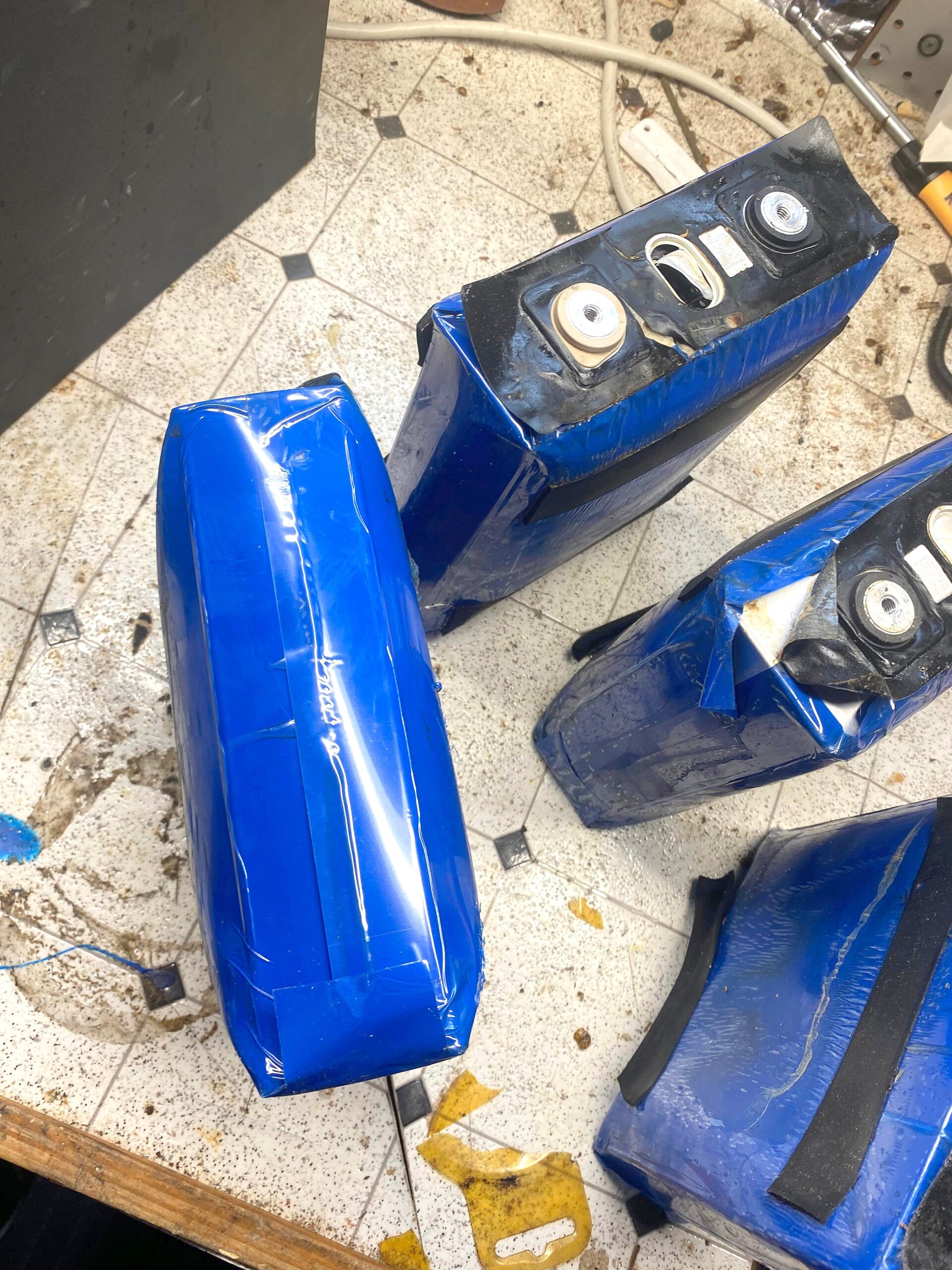
The Cells were overcharged so violently that it blew apart the metal case!
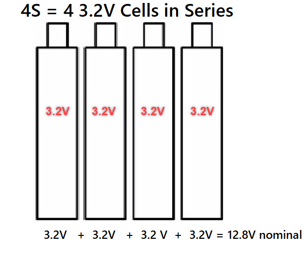
HOW IS A DROP IN BATTERY MADE?
A 12.8 V (nominal) lithium iron phosphate battery is made from four 3.2 V cells wired in series. This is referred to as “4S”. This makes the battery a 12.8 V rated battery. The difference between lead acid and lithium iron phosphate is that each cell in a lead acid battery is a nominal 2 V cell but in a lithium iron phosphate battery each cell is 3.2 V. So, a 12 V lead acid battery requires six 2V cells and an LFP battery only requires four 3.2 V cells.
Start with the Cells & BMS
There are currently three primary cell types used in drop-in LiFePO₄ batteries:
1. Prismatic Cells
These are rectangular “brick-like” cells that nest together in a compact block. They require cell compression to prevent swelling or bulging during charging. In China, this compression mechanism is often called a “fixture.” Proper compression is essential to maintain long-term performance and safety.
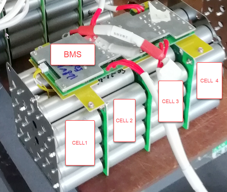
2. Cylindrical Cells
These range in size from a standard AA up to a large D-cell. Their round shape provides inherent structural strength, so they don’t require compression. This makes them very durable and well-suited to mobile or marine environments.
However, cylindrical cell packs require a large number of spot welds to interconnect many small cells in parallel before they’re assembled into series strings. This increases complexity and introduces more connection points—but if done properly, it results in a robust and reliable battery.
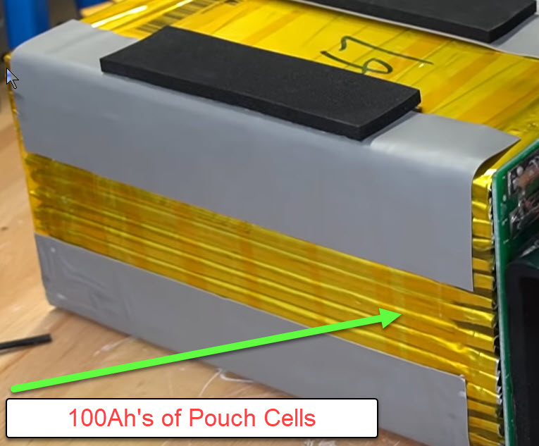
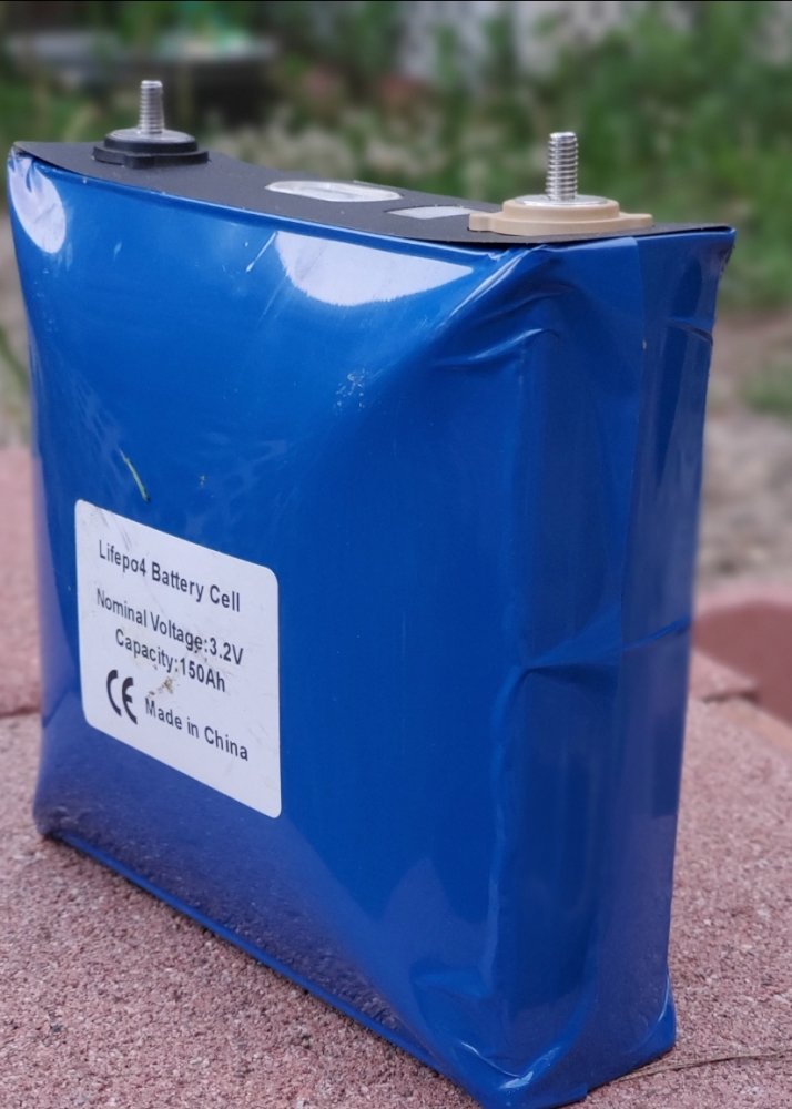
3. Pouch Cells
Pouch cells are flat and flexible, often sealed in a soft foil-like envelope. While they are lightweight and space-efficient, we generally do not recommend them for marine use, especially where vibration is a factor. Pouch cells can be easily punctured or torn, and they are sometimes placed loosely into aluminum cases that may have sharp edges.
Although modern pouch-cell drop-ins have improved and are less prone to mechanical failure than earlier versions, prismatic or cylindrical cells remain the better choice for high-vibration environments like boats.
PRISMATIC CELLS & BMS

CYLINDRICAL CELLS & BMS
Pouch Cells
ADD A BATTERY CASE

Clearly I’ve left out a lot of the important details of the manufacturing of a drop-in battery. In order to build a battery properly the cells must be impeccably matched before the the cell block is assembled. By impeccably matched I am talking about cell to cell Ah capacity and cell to cell internal resistance. If the cells are not carefully matched the BMS inside the battery may never be able to keep up with balancing.We have seen this in numerous instances with drop-in batteries.
What is a BMS?
BMS stands for battery management system. A battery management system is used to protect the individual cells inside the battery. Each 12.8 V (nominal 12 V) drop-in battery must use a battery management system. You could also call a BMS a cell protection system as it actually serves to protect the battery cells inside the drop-in battery. The BMS will protect the battery cells from such things as temperature, voltage, current, cell balance and over-charging. The BMS protects the battery by disconnecting the battery from the charge sources & the loads in the case of over-charging or over-discharging.. Lead acid batteries do not do this. As of about two years ago “over-charge protection” began showing up in drop–in batteries. Over charge protection turns off the bank of charge FET’s when the battery is full thus preventing over charging or over absorbing.
Market Growth – Drop-In Batteries
In the last two years the proliferation of lithium iron phosphate(LFP) drop-in batteries has literally gone berserk. Drop-in technology has finally advanced far enough that I believe it’s now worth discussing in this marine specific article. I had previously avoided this topic because many of the early drop-in products were pretty poorly engineered, BMS’s had weak power handling etc..
Be Careful Who You Trust
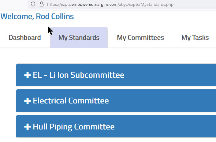
While the internet is full of folks claiming to know what they are talking about sometimes it is easiest to just use a photo. The image below shows the ABYC marine safety standards that I work on. I have been involved with the lithium-ion subcommittee since it was first formed back in late 2013. I was personally invited onto this committee by the committee chair.
I’m also a voracious reader
As can be seen from the image below I have a massive collection of technical documents,research papers& white papers. Everything below is in regards to lithium iron phosphate batteries. I run a 32 inch monitor and I can’t even come close to fitting everything onto one page for a screen grab. This LiFePO4 folder alone has 377 PDF documents on lithium iron phosphate batteries. Yes, I have read them all…

How to Avoid Sleazy Vendors
LFP drop-in batteries have come a very, very long way in the last few years, even the cheap Amazon specials are far beytter than just three years ago. but this does not mean there are no sleazy manufacturers left out there. How do you avoid 98% of the poor LFP products?
Easy; don’t Import directly from China on your own
If you don’t know what I mean by this I would urge you to spend some time on Will Prowse’s YouTube channel but, please don’t focus on his reviews (in a marine application sense), instead focus on how many failures he’s had cutting open & examining drop-in lithium iron phosphate batteries! Please remember that a manufacturer who is sending Will Prowse a battery often knows darn well who he is.. They still fail to send him well-built / well executed batteries many of them lacking cold-weather protection (You can’t charge LFP below freezing) even though they frequently lie and tell him the battery has it. If guys like Will Prowse can’t pick quality batteries out of China how can you expect the average Joe to wade through all the murky information and get good LFP drop-in batteries directly from China?
Hey, I’m not complaining, Will has indirectly sent us a lot of paying customers! These customers have had a number of issues with batteries,cells or BMS’ he’d reviewed. We’ve made a lot of money testing these batteries in our lab, only to tell the customer they had been sent “B-grade or reject cells etc… This sort of stuff, has been sold as “A”grade” but, the customer got “B” grade or reject products. This scammery runs rampant on Aliexpress, Alibababa, eBay, Bangood etc. etc. so be very careful when ordering direct from China because you’re on your own once you do..!
Purchasing- Rule#1
Rule number one for purchasing lithium iron phosphate drop-in batteries is that you always want to buy from a well established US or North American company or a Chinese company with a proven track record. !This site is read world wide but is still a US based company.,Insert Germany UK, Norway, Sweeden etc. for USA), even if that company is having the batteries manufactured in China.
Currently all lithium iron phosphate cells are manufactured in China. Some US manufacturers such as Battleborn, feature US assembly. This allows them to better control the assembly quality, though I have never liked Battleborns construction for a mobile environment. If you desire good support etc., you’ll want, a presence here on North American soil (insert your country here) to ensure that the company can stand behind the product and you are protected by US (insert your country) consumer laws.. There are m,any Chinese companies with good support, however it will not be as fast as picking up the phone..
Most of the “bad” images you will see below are what happens when a DIY attempts to become the importer of LFP batteries.
What About the ABYC?
ABYC has re-written TE-13 which no longer requires visible/audible alarms among other things. Insurers now have very little they can say about LFP.
“Rod, isn’t the ABYC is a “voluntary” standard?
Absolutely, but here’s the rub, every marina in the United States, and most in Canada, require insurance. If your vessel is insured the insurance company has standards they expect. In North America those standards are the ABYC standards. They use Marine surveyors to ensure the boat is safe and up to their underwriting standards. Marine surveyors are currently using ABYC E-13 as a guide for LFP installations and are actively calling out installations that don’t meet the nature of the E-13 document.
An ABYC E-13 compliant installation is what you want to strive for.
YouTube Influencers?
Are They Marine Focused?
Are they ABYC Electricians?
I really do like like Will Prowse and he’s doing the general public a tremendous service in cutting open all these drop-in batteries and exposing all the dirty little secrets. We too have cut open a slew of these batteries I just don’t do video or video editing well.. The problem I have with Will is that he does not operate in the marine environment and the marine environment is a different set of circumstances & standards than it is for RV or off-grid cabins. For example, I don’t know a single RV that has a 12V bow thruster that can pull over 600A(no load rating) at 12 V and 1600A+for in-rush LRA/FLA rating. An in-rush like this is capable of ruining some FET BMS boards especially after repeated thrusts. For example, Will, and many others, highly praise Battleborn yet, we have never advised them for a mobile or marine install due to the internal construction, which is just not up to our standards..
Is Your Vessel a Good Match for Drop-In Batteries?
Use this flow chart to find out
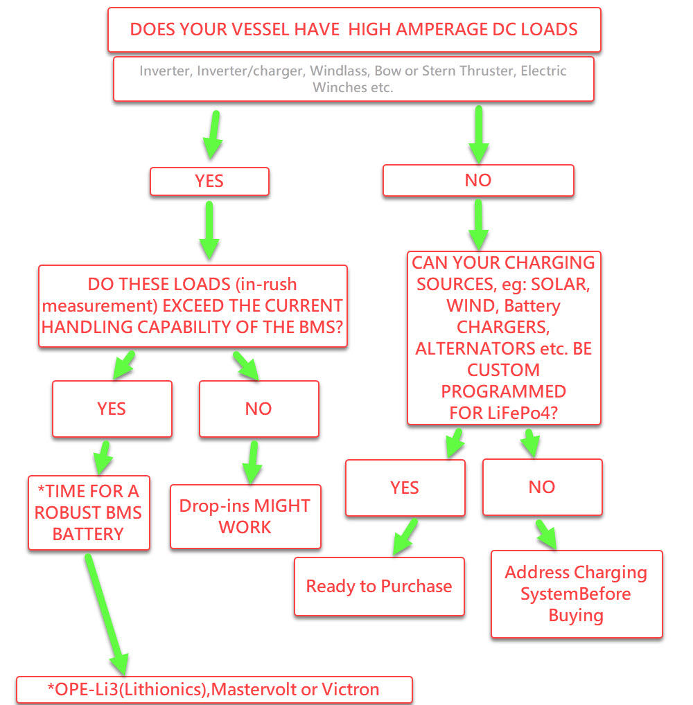
An upgrade to lithium iron phosphate batteries can always be done in stages. We typically advise starting with the charging system first, as your on-board items become antiquated or become failure prone. We suggest upgrading any sort of charge equipment eg; solar controllers, alternators or alternator regulators with devices that can be fully programmed for lithium iron phosphate batteries in the future.Doing this as the items begin to become failure-prone means that in the future when you’re ready to upgrade to lithium iron phosphate batteries your system will be ready for it.
“A Grade” = Marketing BS
Please understand that the term”A Grade” is really a meaningless-term in China. “A-grade” really means EV/automotive-grade but the Chinese have figured out that people think “A”grade actually means something…Depending on the seller it may actually mean Abhorrent or Abysmal grade.
For boaters buying drop-in batteries direct from China this can mean the low-grade “orphaned” or “rejected” cells wind up in batteries that may look exactly the same but are sold on Ali-xxxx, , eBay or through other less reputable sources.. Once the cells are sealed in its glued together plastic case you the buyer have no way to know what quality cells you got.
Important BMS Considerations
Current Handling
The current rating of the internal switch that protects the battery is quite often too small for the task on many cruising boats. Drop-in LFP batteries routinely use multiple tiny little MOSFET switches as the batteries BMS protection ON/OFF switching. Unfortunately these FET’s often can’t handle the typical loads imparted by many cruising boats. On board devices such as bow thrusters (400A +), windlass’ (100A to 300A+, large inverters 150A to 300A +, electric winches 75A to 300A +, electric cook tops, massive alternators, chargers or large inverter-chargers are very very common on-board cruising boats these days. These are exactly the devices many boat owners are hoping to see a gain in performance from when switching to LiFePO4.
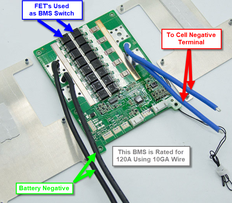
This is what a 120A rated FET based BMS looks like it is pretty for a typical 100Ah drop in battery. This is what an internal FET based BMS boards typically looks like with the heat sinks removed. The blue wires connect to the neg end of the cell string and the black wires are connected to the external negative battery post.fet bms’S DISCONNECT ON THE NEG SIDE OF THE BATTERY This one uses two 10GA wires for its 120A continuous rating. All 120A has to pass through those two 10AWG wires, the printed circuit board and the FET’s. The hotter FET’s run the shorter the MTBF (mean time between failure) is. This Particular BMS ,a JiaBaida, uses 32 FETS(the board has double sided FET’s. We have cut open drop-in batteries with 100A rated BMS’s ( that use only 10 FET’s.(see image below this one)..
Important: For those going with all electric boatseg: air conditioning, electric range and massive inverters we suggest not discharging any FET battery at more than 50% of the “continuous” rating. We also do not advise charging any FET BMS battery at more than .2C. Following these two basic rules will ensure your BMS lasts…
What a FET BMS Looks Like
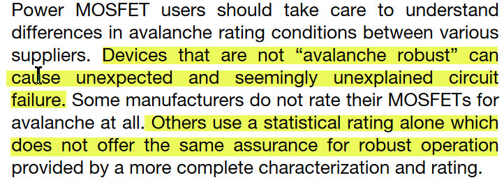
FET QUALITY MATTERS
 High-Current DC Devices?
If you own a vessel with high load devices, do yourself a favor and look at the contactor ratings (the BMS protection switch) that “marine specific” companies such as Lithionics/OPE-Li3, & Mastervolt use for their”marine specific” LFP batteries. What you’ll often see is a 500A continuous rated Gigavac, Blue Sea ML-RBS, Tyco EV-200, or in the case of Lithionics, military grade 500A contactor/relays are being used as BMS protection switches.
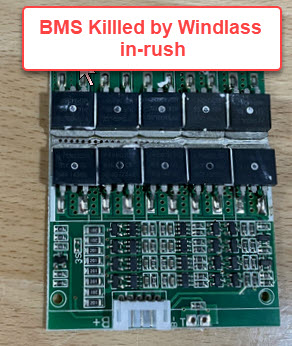
A Dead FET BMS (windlass in-rush)
Below is the BMS “switch” used by Mastervolt on their MLI series LiFePO4 batteries. It can handle bow thrusters, large windlass motors, massive inverter-chargers, massive alternators. etc.. The ML-RBS switch is rated for 500A continuous, 700A for 5 full minutes and 1450A for as long as 30 seconds. While many smaller boats can often get by with a FET based BMS, not all boats can, so please consider the max continuous discharge and recommended charge ratings of the battery you are purchasing. This rating is not usually limited by the cells but rather the internal BMS’s current handling capabilities.
Let’s take a look at the BMS switch Mastervolt uses. (Lithionics uses a similar switch on their external BMS batteries.
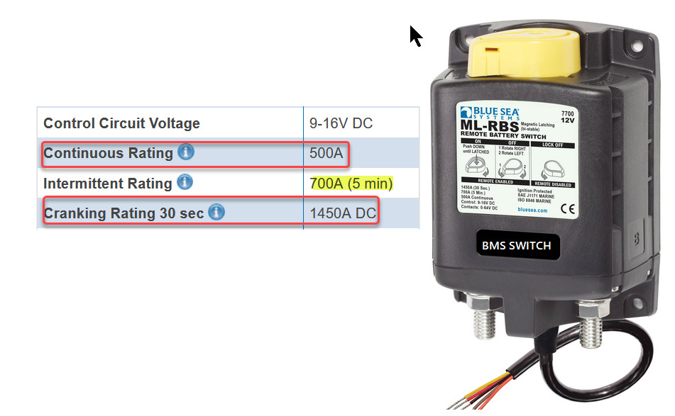
You read that correctly
500A continuous or 1450A for as long as 30 seconds!!!
Sadly, when buying direct from China,you can still find diminutive 50A continuous rated FET switching BMS’s installed inside a 300Ah LFP battery. As a comparison a 150Ah KiloVault can handle 150A continuously or 200A for as long as 30 minutes. While a 50A rated BMS may be fine for small boats, if you have large on-board DC loads, or want to charge a 300Ah battery quickly, then a battery like this is going to be a less than ideal battery for marine use. So, you still really need to do your homework to make sure the batteries & the internal BMS are a fit for your vessel.
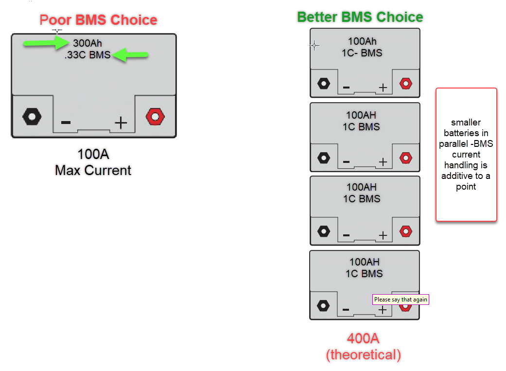
Assembling a Drop-In Bank for Large DC Loads
When it comes to FET based BMS batteries we typically advise smaller individual batteries, wired in parallel. This is done to share the load across the FET based BMS’s. For example three 100Ah / 1C rated LFP drop-ins can theoretically handle a 300A discharge, if the parallel wiring is perfect and all batteries share the load equally(rarely happens that way.) A 300Ah 8D format drop-in, like the one addressed below, can really only handle a 100A (0.33C) discharge. When in doubt with FET based BMS systems smaller batteries in parallel are usually a better solution than one large battery with a low current rated BMS.
A Drop-In Battery Spec sheet SHOULD Look Like This
*Highlighted specifications are the critically important ones.
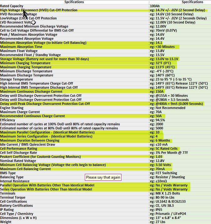
Minimum Absorption Voltage (to Initiate Cell Balancing): This is important because you need/want to activate balancing with each charge cycle. You also want to avoid pushing to the maximum charge voltage every cycle if you wish to maximize cycle life.
|
High Internal BMS Temperature Discharge Cut-Off: same as above but for discharging.
|
If you are unfamiliar with what the specifications mean or why they are critical you may want to reconsider drop-in batteries until you have completed the research phase.
Vibration
Some of the very cheaply sourced drop-ins are using 18650, 26650 or 32650 cylindrical cells inside the battery case. In a worst case, a 100Ah LFP battery, built from 18650 cells, would need a grand total of 364 cells with two connections per cell.
How’s that math work?
18650 Cell = 1.1Ah (typical Ah rating for an 18650 LFP cell)
91 Cells Make Up Each 3.2V cell
Four 3.2V Cells Make Up a 12.8V 100Ah Battery
91 X 4 = 364 18650 Cells
Positive & Negative Connections Inside The Battery = 728
If the manufacturer uses 5Ah 32650 cells, and some do, we then only need 80 cells total, and 160 spot welds or bolted connections to potentially fail or work loose. (32650 cells are available in bolted or spot weld versions)
The connections, with 18650s’s, are almost always spot welded to end boards that make up the individual cells. So, in a single 100Ah battery, made of 18650’s, just to connect the cells, we have as many as 768 spot welds to rely on. Beyond that we have all the internal wiring and BMS connections. These spot welded assemblies are often just dropped into the polypropylene case with no other support or vibration dampening material. To be safe, always be sure to ask the battery supplier to furnish third party vibration testing results or testing to UL or IEC vibration standards.
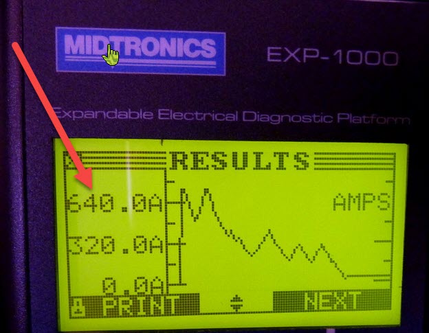
DC Motor In-rush
The reason most drop in batteries cannot be used for starting is the in-rush current. The in-rush of large DC motors looks like a dead short to the FET’s. Imagine sitting there and intentionally shorting your battery multiple times each day…..That is what starting your motor, running a windlass, electric winch or Bow thruster looks like to the FET’s. There are LFP batteries that can be used for starting but they are very expensive at this point in time.
Starting a 40HP Westerkeke takes=640A!!!!
Cylindrical-cell battery failure
Cylindrical cells are great performers but like anything the devil is in the details. Do you know how well your battery is put together? Battleborn uses
Cylindrical cells and their construction is not something we advise for mobile applications.
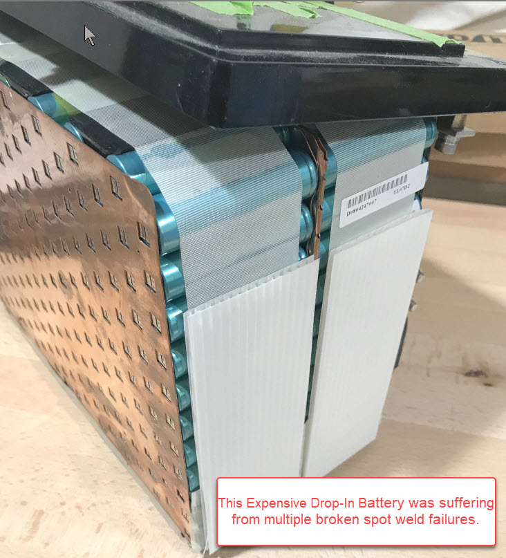
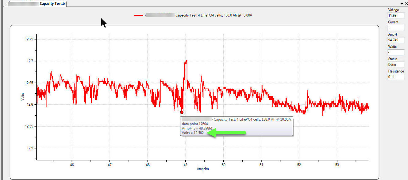
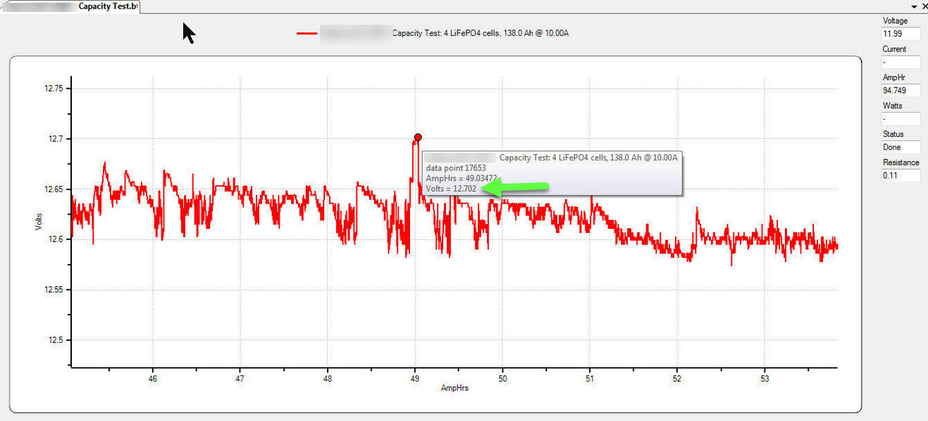
How did we discover the spot weld failures? The zipper like discharge graph was a dead giveaway.. After a discussion with the manufacturer we had to tell the customer to stop using his bank immediately…It had also lost significant capacity from over charging. His lead-acid charger that held 14.6V way too long 4 hours on every cycle. We were testing them for capacity when we discovered the spot weld failures (brand purposely obscured). In the screen grabs below you can see how varied the voltage was on discharge.We had wanted to run the discharge at 40A but the zippered graph was even worse at 40A so we ran the capacity test at 10A..
Data point =12.582V
Data point = 12.702V
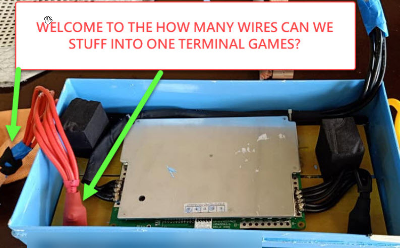
 Internal Wiring Shortcuts
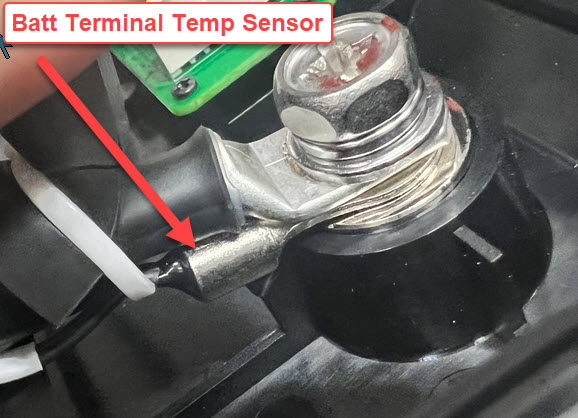
What happens when you cram multiple small wires into one terminal and ask them to carry 100A +/-Hint: You get terminal melt down.. Epoch batteries has a positive & negative terminal temp sensor to identify high resistance before it starts a fire. FWIW, this is one of the most expensive batteries on the market!

Here’s what they look like when you hit them with thermal imaging.

The Internet said LiFePO4 is 100% safe
No battery chemistry is 100% safe, especially when you over charge it.(However no-fire , no-flames & no explosion just cell swelling and heating… FWIW this “starting battery” has zero BMS Protection. A BMS is required under ABYC and ISO.
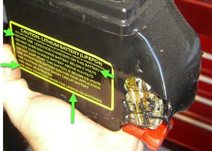 Image courtesy MHT Reader
Prismatic Cell – Over-Charged
This is what over charging looks like.
Cell Compression/Containment
Below is what proper cell compression for aluminum prismatic cells looks like. Has your chosen manufacturer included this? Lots of manufacturers use thin-wall aluminum cells just dropped into a plastic case.
What Good Quality Looks Like
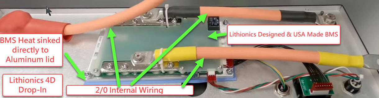
Thhe photo below is a Lithionics G-31 drop-in battery. This battery uses impeccably matched aluminum encased 5c LiFePO4 cells. The cells are fixed in place by an injection molded jig that protects them from movement and vibration failures. The busbars are high grade nickel plated copper and self locking flange/wizz nuts are used to hold the cells to the busbars. The BMS used in this battery is certainly FET based but it is made here in the USA, of Mil-Spec components, and is made by lithionics. Sadly, these batteries are insanely expensive!

Epoch
For the price and feature level these batteries simply cannot be beat. The image below shows a feature that goes far beyond any brand we’ve seen. Epoch puts a temp sensor on the positive and negative terminals to protect the battery if there is a high resistance connection.
Internal Wiring
It is not uncommon to open a 100Ah drop-in battery, rated at 1C, and find a single 10GA or 12GA wire feeding the main positive and negative terminals. When someone finds a 10GA or 12GA wire rated for 100A, under any safety standard, please let me know?
Lithionics 320Ah drop-in.
BMS Shortcomings
Lack of low or high-temp Protection
Some of the drop-in batteries may lack BMS temp protection altogether . Drop-in batteries should have both low and high temperature protection (a requirement for both ABYC and ISO) but many don’t. Far too many drop-in batteries lack low temp protection and a large number of manufacturers who claim it has low temp protection are actually lying about it. If You live up North,buyer beware!
Non-Communicable BMS
For a trolling motor, who cares? It’s not powering anything critical. For a house battery, on a cruising boat that ventures off-shore, and is powering critical navigation and safety equipment, this can create a dangerous situation. A non-communicable BMS is one that cannot communicate externally with the vessels charge and load systems, or even you the owner. It has no means of externally communicating or sending/sounding warning alarms or activating relays/triggers to properly and safely disconnect charge sources or give ample warning of an impending BMS disconnect. Some batteries are now featuring Bluetooth monitoring but this still requires you the owner to be watching it.
Let’s take a look at one of the worlds most respected marine standards for shipping etc., Bureau Veritas.
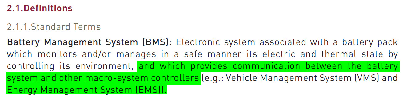
As can be seen, under Bureau Veritas standards external communication between the battery and the rest of the systems such as charging is a requirement. For why see below.
WHAT ABOUT CHARGING?
LFP batteries are charged using a CC/CV profile. This means constant-current/constant-voltage
Bulk = Constant-Current(charge source working flat out or as hard as it can)
• Absorption = Constant voltage( voltage is held steady for a short time or until current declines to the manufacturers spec.
• Absorption Duration = Once the batteries have achieved the absorption voltage the time the batteries spend at this voltage must be limited. Many lead acid charge sources spend far too long in absorption and this is not healthy for LFP
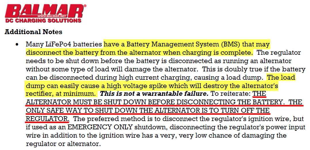
BMS LOAD DUMPS
DON’T FORGET YOUR ALTERNATOR
email from MHT reader:
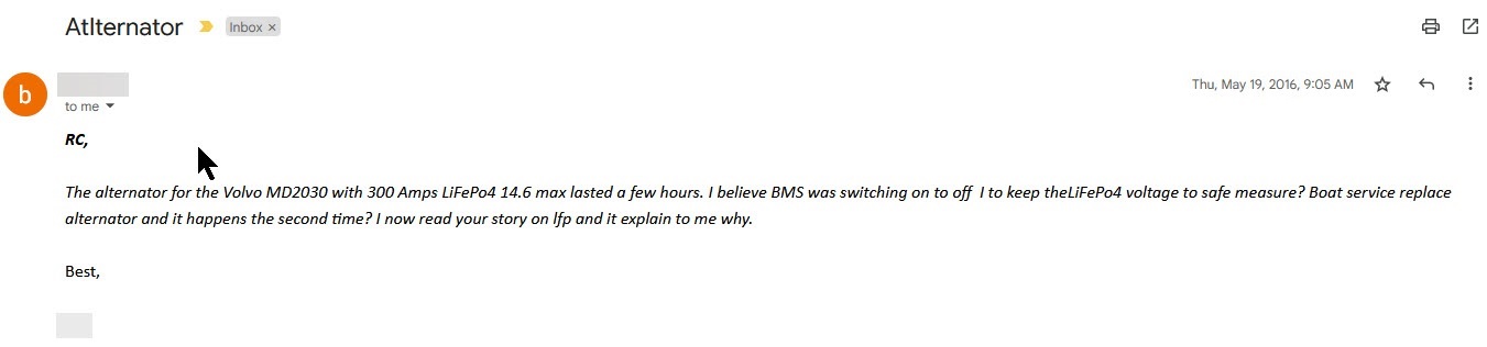
Unfortunately the reader above learned the hard way. Ask yourself what happens when your alternator is in bulk charge, supplying all the current it can, and the internal BMS decides to “open circuit” or disconnect the battery from the boat? I’ll help out a bit here.
BMS Load Dump Illustration
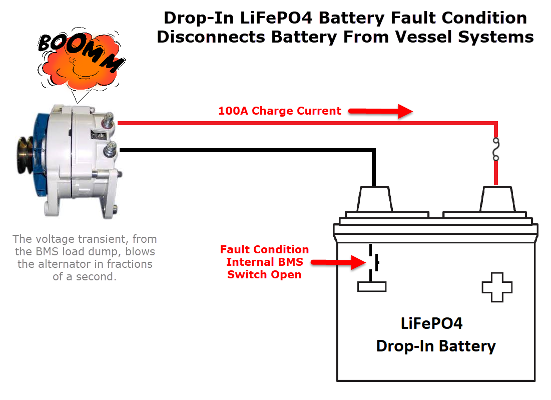 What a Load Dump looks like
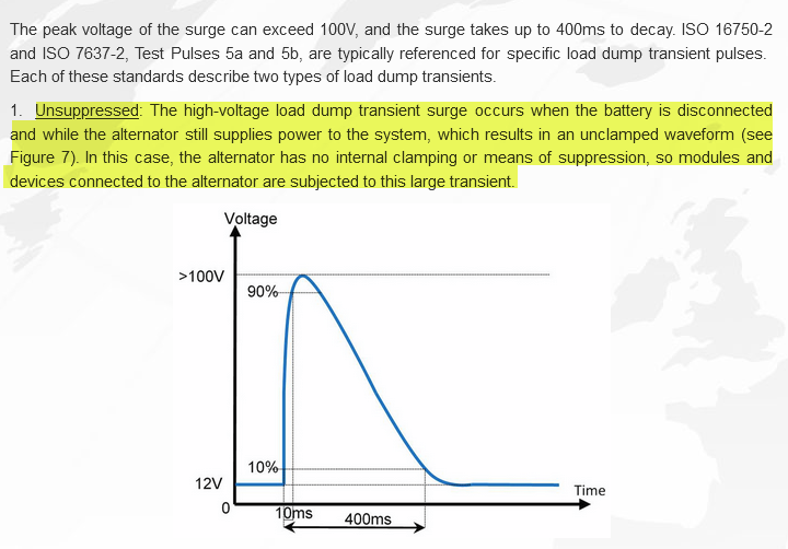
The load dump transient captured in the above image is from an ISO test of a 12 V automotive alternator. Of important note is how quickly this transient surpasses 90V.
Surpasses 90V in just 0.01 seconds
A) The alternator diodes, unless avalanche style, (rare in many existing marine alternators)can be blown.All Balmar alternators now use avalanche diodes, Two years ago we did exactly this. Using the alternator test bench here at CMI the 90A alternator was running at full bore charging an LFP battery. The “system” I set up had a .3A dummy load on, a light bulb, to simulate a depth sounder. With the alternator running at full bore I disconnected the battery, just as an internal sealed BMS can do for BMS temp, cell diff-voltage or cell high voltage. Poof went the alternator diodes and the light bulb was burned instantaneously! Worse yet the voltage transient I recorded on the “load bus” (think your navigation electronics) using a Fluke 289 was 87.2V. Ouch. Even if your alternator uses avalanche diodes, like Balmar’s do, the voltage at which they begin to protect the alternator is far too high for the vessels load bus equipment so you still need a way to protect against a load dump.
B) If the boat is wired, as is typical with drop in batteries, the voltage transient caused by the open circuited alternator will now directly feed the DC mains and potentially destroy your navigation equipment.
TIP:
At a bare minimum, every drop-in LFP battery bank, that can be charged via an alternator, should be installed with an Alternator Protection Device. We like both the Sterling APD and the Balmar APM.
Buy a Sterling Power Alternator Protection Device
Buy a Balmar Alternator Protection Module
A well designed marine specific BMS would open a relay that can de-power your charging sources on the input side, thus shutting the charge sources down correctly and safely with no risk of a damaging voltage transient. For a large inverter/charger it would de-power the AC input side, for an alternator it would de-power the field wire or regulator B+, for solar it would open a relay in the PV feed etc. etc.. With a drop-in battery, that features a sealed BMS, you have no way to do any of this. Only Lithionics Drop-In Batteries have this Capability.
What If program my sources below the BMS disconnect?
Sounds like a good plan right? Well, lets examine the most common reasons a BMS can disconnect
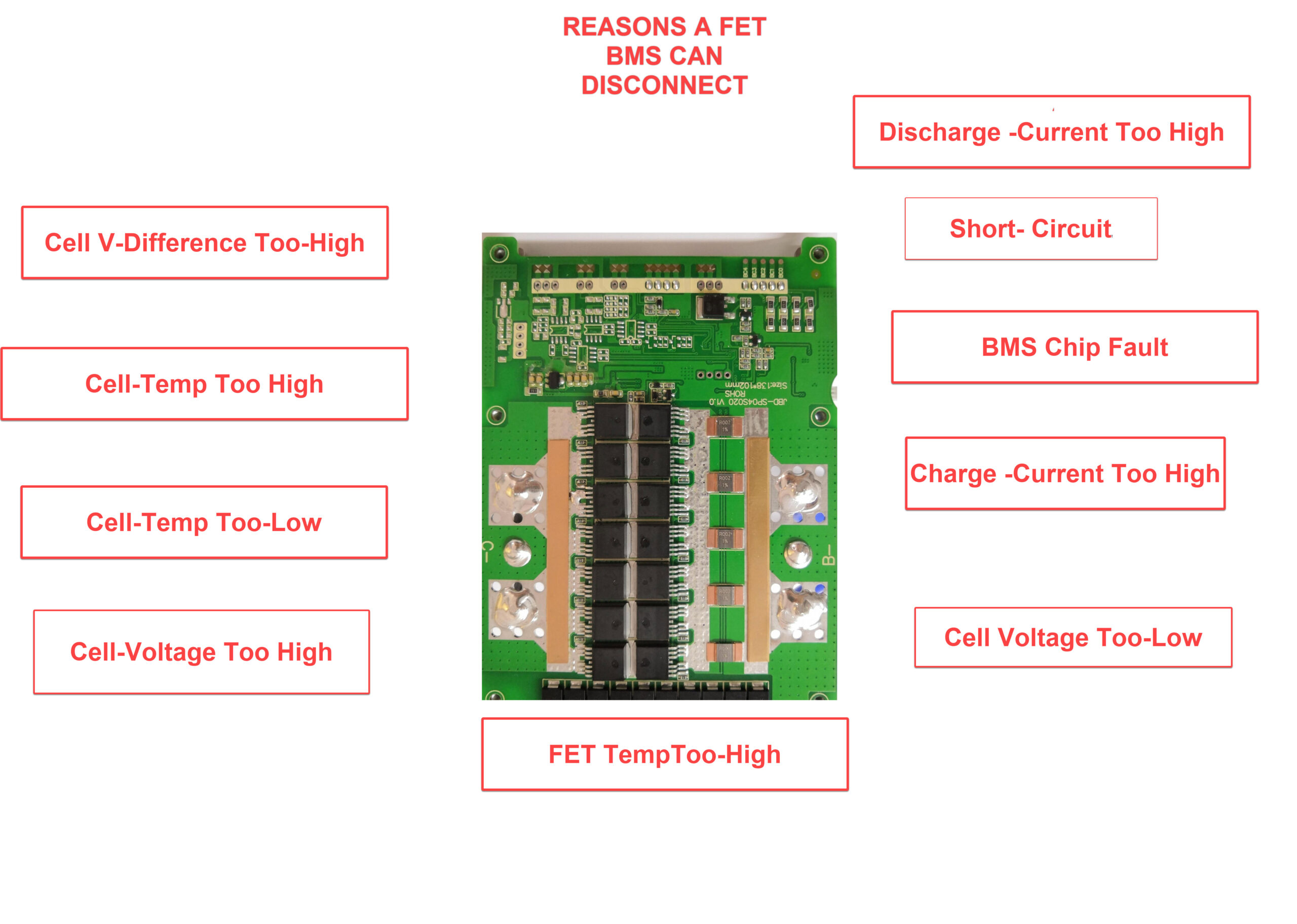

programming a lower charge voltage can’t always protect against a BMS disconnect
Are BMS Load Dumps Real?
I’ll let Balmar Explain this;
How about a fairly knowledgeable owner who bought a very beefy alternator and still killed it due to BMS load dumps.

D
The number one reason we see batteries shut down(when everything is programmed correctly) is almost always due to BMS temp related issues not necessarily high cell voltage.. When dual-channel FET BMS’ started showing up in 2014 or so load dumps became pretty rare because the can shut off charge but still remain connected to the load. If thew load is big enough it absorbs the spike. Prior to about 2014 dual channel BMS’ were very rare.
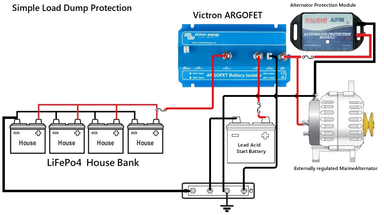
Mitigating Load Dump Damage
A good technique to mitigate load dumps is to keep a buffer “load” on the charge bus at all times (Buffer load = lead acid battery on the systems charge bus (see the Victron ARGOFET Isolator wiring below). With FET isolators, we like to see them at least double the rating of the alternator eg; a 200A ARGOFET for a 100A alternator. The cooler FETs run the longer they last. And yes, we have seen FET isolators fail…
Buy Victron Argofet – Bay Marine Supply
Load Dump Work-Around’s
Using Low Volt-drop FET Isolators with an externally Regulated Performance Alternator
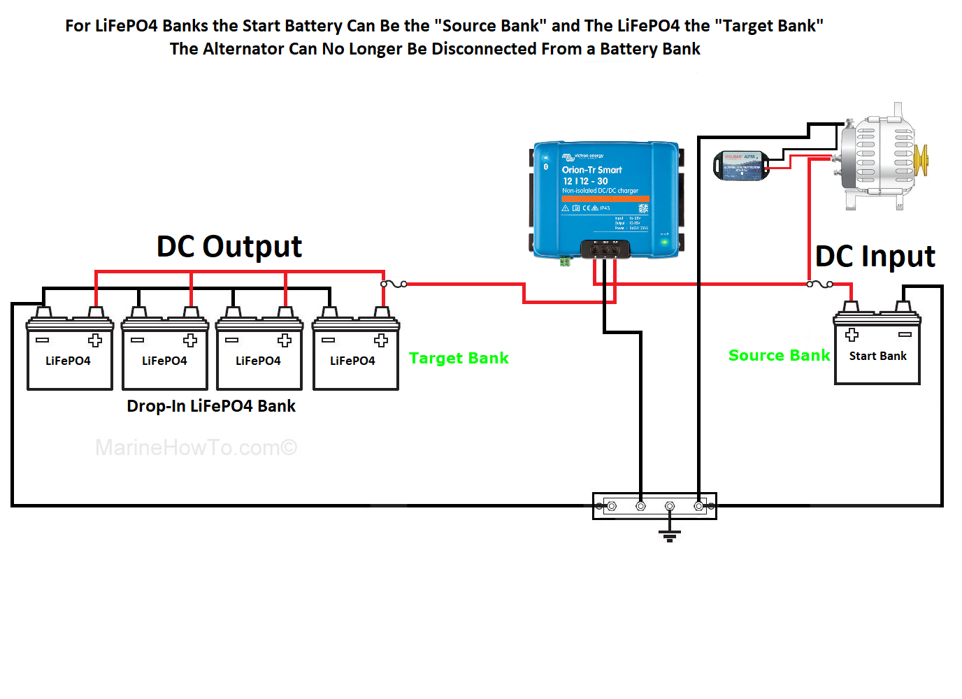
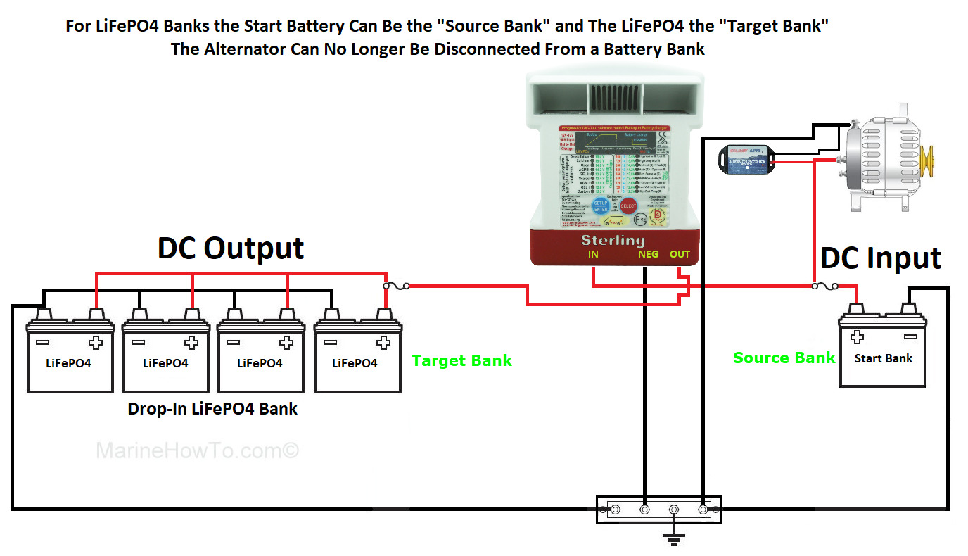
USING DC to DC CHARGERS
There are many benefits to using DC to DC chargers. One of those benefits is that the charge profiles can be custom configured to charge lithium iron phosphate batteries where your factory alternator or legacy lead-acid charge equipment cannot be programmed for this. The Victron Orion TR Smart and Sterling power DC to DC chargers can also absorb a load-dump from a BMS disconnect where your factory alternator cannot.
Sizing a DC to DC charger
Caution needs to be used when sizing DC to DC chargers. A DC to DC charger should be sized at a maximum of 50% of the factory alternators rated output. This means if you have 100 amp factory alternator the maximum DC to DC charger you should use is 50A. This will help keep the alternator cool and keep it from burning itself up. Currently there are only two DC to DC chargers we recommend and those are Sterling Power and Victron.
The only drawback to using DC to DC chargers is that you give up charging your lithium ion phosphate batteries quickly. Seeing as that is one of the major benefits of LFP batteries we would strongly advise considering an externally regulated alternator with an external regulator such as the Arco Zeus, BamarMC-618 or Wakespeed WS-500 these regulators can be programmed for LFP and have an alternator temperature sensor to protect the alternator from heat damage. This will also result in considerably faster charging!
Using DC to DC chargers Results in Slower LFP charging
CAN I USE MY STOCK ALTERNATOR?
The short answer is we do not advise this for charging lithium iron phosphate batteries directly. You can however use your stock alternator if i it is behind a DC to DC charger that serves to protect it and that provides the proper charge profile for the lithium iron phosphate batteries.
WHY?
1-A stock alternator rarely has the correct charging voltages for lithium iron phosphate batteries.
2-They can over absorb the batteries resulting in over-charge damage
3-The absorption voltage is very often too high (see below)which can lead to BMS load-dumps
4-Stock alternators do not FLOAT, they only do bulk and absorption.
5-Alternator heat damage
Do You know the voltage set point of your stock alternator?
We have been an alternator manufacturer for more than 15 years so we understand internal vs. external regulators and how these alternators are built. We also have access to data, such as you’ll see below. This is data the average DIY would never have access to.
Max Charge for a 12V drop-in battery is 14.6V or Lower.
Common Internal Voltage Regulators
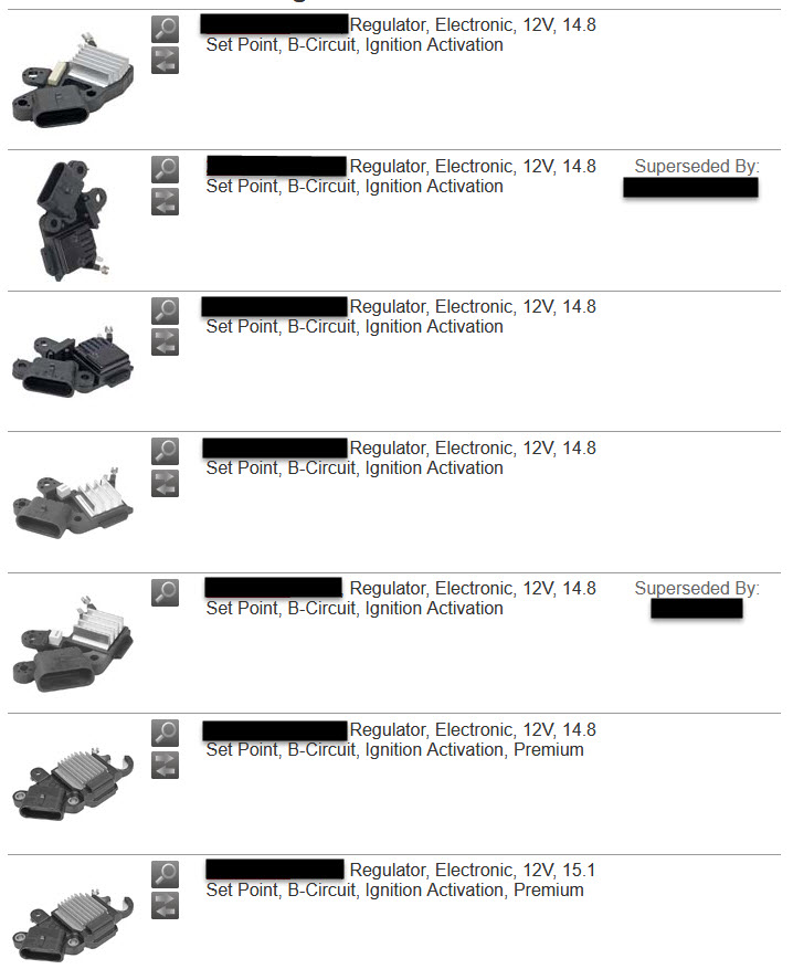
IF your BMS Disconnects at 14.6V / 3.65VPC a reg with a 14.6V set-point is likely to cause you BMS disconnect issues.
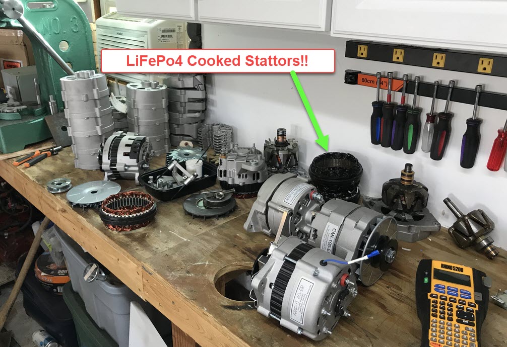
Alternator heat damage
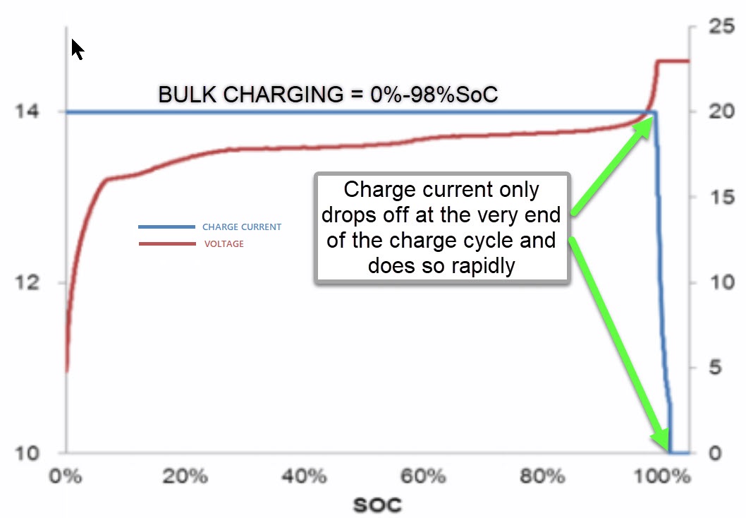
LFP batteries have a tendency to enjoy eating alternators for lunch. The internal resistance of LFP batteries is extremely low resulting in very long bulk-charging times. As a result alternators can burn themselves up trying to charge these batteries. I’ve said this many times before on the site and I will say it once again, there is no such thing as a small frame alternator that is continuous duty, I don’t care who built it, they all need temp protection!
Because Compass Marine inc. was a manufacturer of marine alternators so we got to see these failures regularly. We are not an n=1 data point like the “dude on the internet” who says your stock alt will be fine charging LFP. We have seen far too many alternators completely melted down by LFP batteries to ignore this information..
If you insist on using your stock alternator we would strongly recommend that you put it behind a DC to DC charger (50% smaller than your alternator amperage rating. This will help limit the amount of work the alternator is doing and protect it from a meltdown.Doing this means you can continue to use your stock alternator.
If you expect to charge lithium iron phosphate directly from the stock alternator without a DC to DC Charger in-between, we advise not changing a thing. Do not increase the wire size to the battery bank ,do not move the volt sense a wire do not touch zdthe factory wiring .Doing so can result in an alternator meltdown. The typical factory wiring on these alternators is horrible and results in a lot of voltage drop. That in and of itself can help protect your alternator from melting down.
Why does LFP cause heat damage?
It is very simple your alternator never catches a break!
Our Alternator Assembly Bench on a Typical Day..
Don’t be this guy!
ImageCourtesy MHT reader

Stock Yanmar/Valeo Alt Cooked
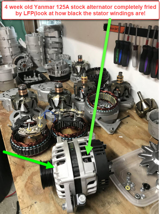
Yanmar/Hitachi alternator Cooked

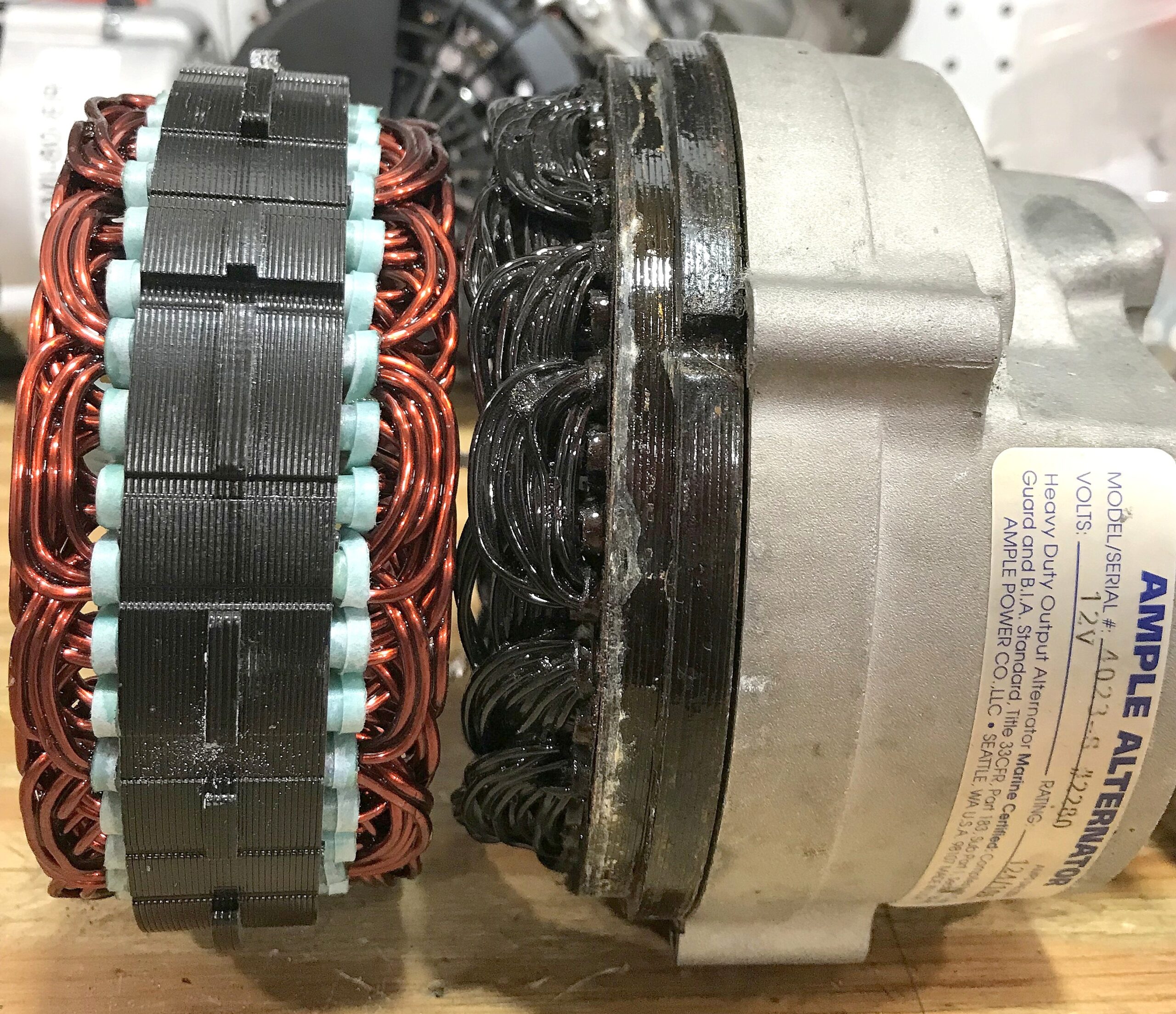
Burned up Stator From Charging LFP
Another One
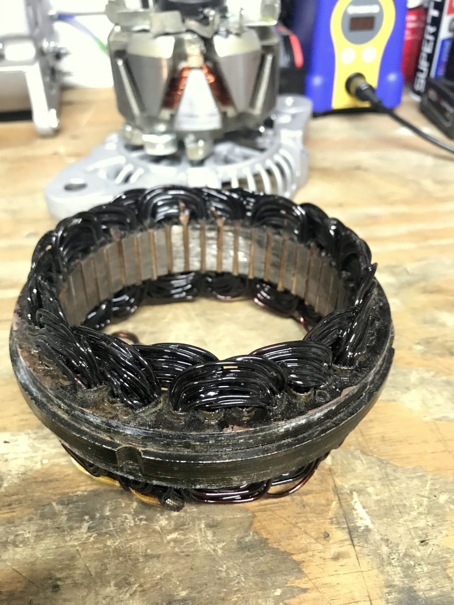
Another LFP Cooked Alternator

But, Ample built good alternators?
Yes, they did but during this vintage Ample Power did not believe in using an alt temp sensor on their regulators.. When LifePO4 came around…This alt ran fine for 20 years charging lead acid. Within weeks of converting to LFP, toast!
Series Wired Systems ?
In a parallel wired bank one battery BMS dropping out only creates problems when it re-engages into a different SOC than the rest of the bank by causing a large in-rush. With a series bank (for 24 V 36v or 48V a single BMS taking itself off-line spells disaster at sea and takes out the entire bank. I know a Drop-in owner who hit a granite bridge abutment in his electric boat using a 48V series bank of drop-in batteries. It did a few thousand in damage to the boat, and his pride, but it could have been much worse. The owner had zero warning the battery was about to disconnect itself before he lost all propulsion power. This failure occurred going under a drawbridge in a very strong tidal current. If you wire drop-in batteries in series please use an external series balancer.
CHARGING LFP WITH OTHER SOURCES
LFP batteries are charged using a CC/CV profile. This means constant-current/constant-voltage
Bulk = Constant-Current(charge source working as hard as it can see burned up alternators above)
• Absorption = Constant voltage( voltage is held steady for a short time or until current declines to the manufacturers spec.
• Absorption Duration = Once the batteries have achieved the absorption voltage the time the batteries spend at this voltage must be limited. Many lead acid charge sources spend far too long in absorption and this is not healthy for LFP.
Do you know what this means?

max charge voltage 14.6V
max charge current 20% of installed Ah Capacity
When at 14.6V all charging must stop when accepted charge current has dropped to 0.02C or 2% of installed Ah capacity
Can Your existing charge system do this?
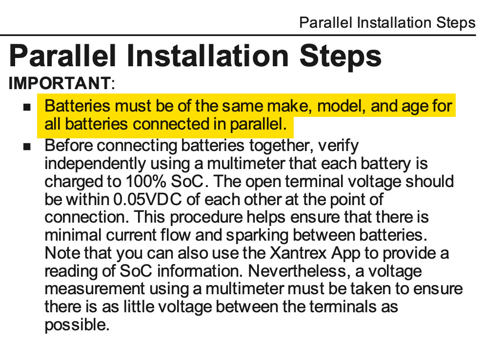
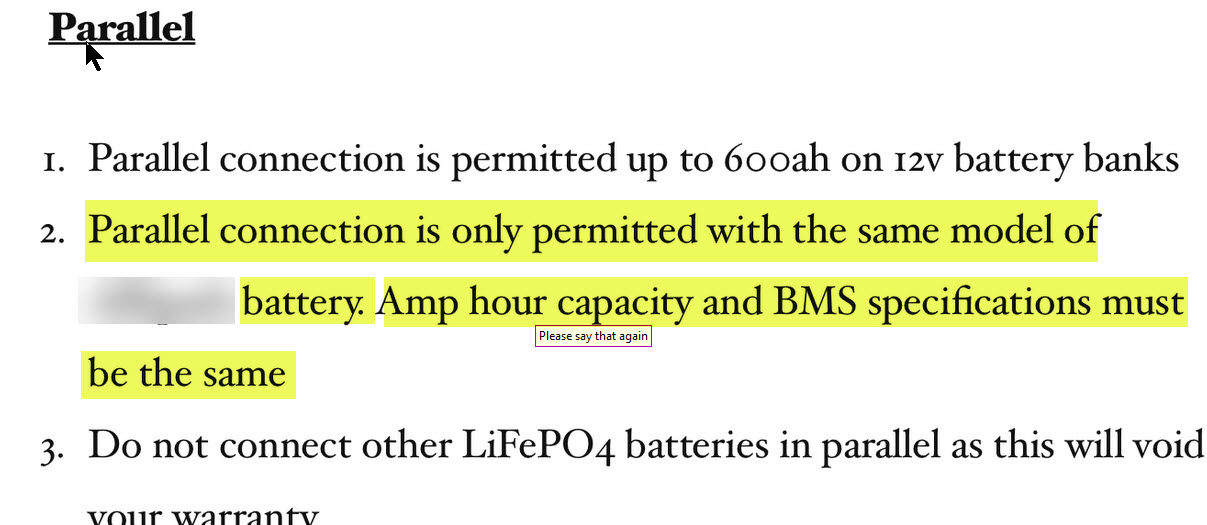
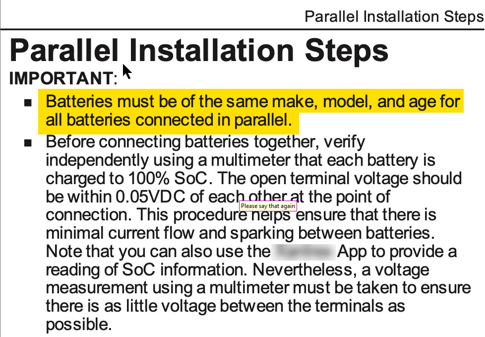
Pay Attention to Small Details

When installing these LFP batteries in parallel the max charge voltage is just 13.8V-14.2V (it’s 14.6V for a single battery “small details”)
Max charge current is 50% of installed Ah capacity or .5C.
When at 13.8V – 14.2V and charge current has fallen to 5% of installed Ah Capacity all charging MUST STOP
Can Your chargers do this?
 Can Your charge sources be programmed for these parameters?
Series Solar Warning!
Over the last few years on boats one of the trends that can be a little terrifying has been that solar panel array voltages have been creeping up and up.. Many boat owners want to install their solar panels in series and then run them through an MPPT controller to maximize the energy capture of the array.
This is all well and good until there is an issue and the MPPT controller fails. Imagine what happens if you’re MPPT controller fails and starts passing PV voltage through to the batteries? If your array is over 60V & these are lead acid batteries they will eventually explode. If they are lithium iron phosphate drop-in batteries you will toast your BMS! Once the BMS is been fried by the solar array voltage you have no BMS protection & the solar array will continue feeding dangerous voltage to the batteries until they are destroyed. You can imagine what will happen if this continues to go on after in an MPPT failure. In case you’re wondering yes, these failures have happened and lithium iron phosphate batteries have been destroyed due to this. These failures almost never occur in tier-top tier supplier MPPT’s.
How do you avoid this?
#1-observe the maximum number of series batteries you can wire for. With most brands limit this is 24 V or 48 V. This voltage is typically the maximum SAFE voltage the battery bank BMS CAN handle. So, your PV array should not exceed this voltage.
#2 if you wish if you wish to use series-solar on your vessel you will be safer to split the array into smaller series strings that remain below the batteries maximum series allowable voltage and give them each their own MPPT solar controller.
#3 Use only top tier MPPT suppliers (eg; VICTRON, OUTBACK, MIDNITE, MORNINGSTAR ). These controllers use isolated input/output and are designed not to fault in a manner that passes full PV voltage through to the batteries..
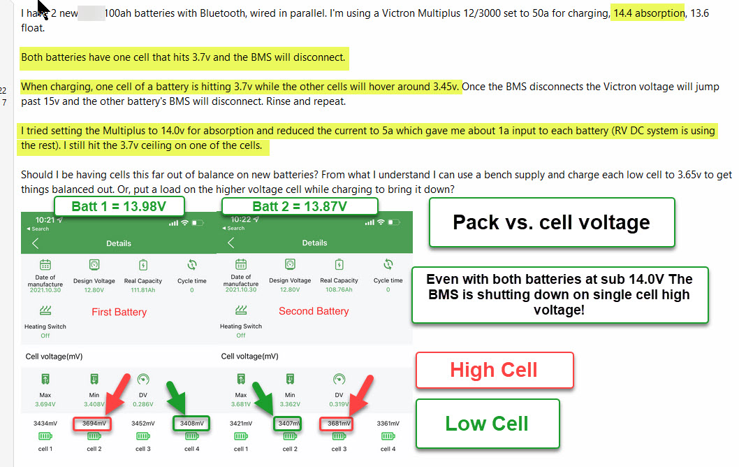
Pack Voltage vs. Cell Voltage
Pack voltage tells you nothing about cell voltage as can be seen below!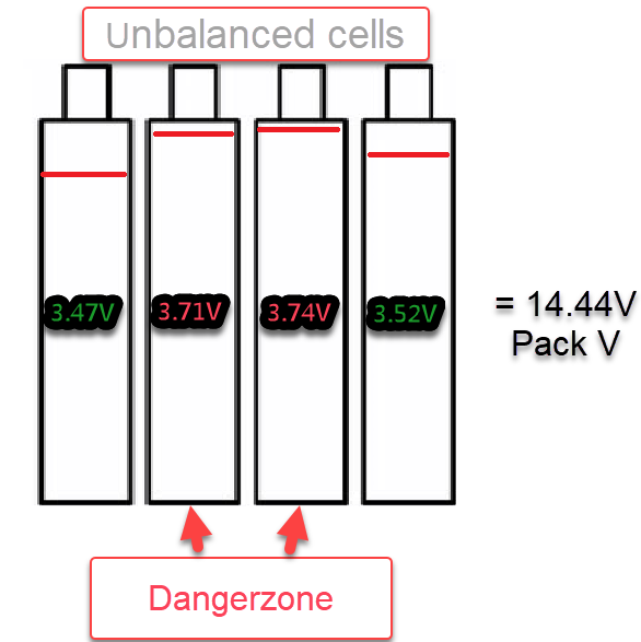
Know your loads before you buy!
The critical load data you need to know is the in-rush current for all DC Motors .This includes a windlass, electric winches or a bow thruster. You also want know your inverters Pre-charge in-rush. Unfortunately most DC Clamp meters cannot properly capture DC in-rush current. We own three DC clamp meters that claim to do in-rush but all except the Fluke meters fail miserably. The image below is one of our Fluke 376 meters capturing the in-rush current for a Lewmar V2 Windlass. This customer ruined his FET BMS (seen in an image above in this article) by using his “direct from China” drop-in battery to power his windlass. Warranty? Ha-ha now that’s funny….
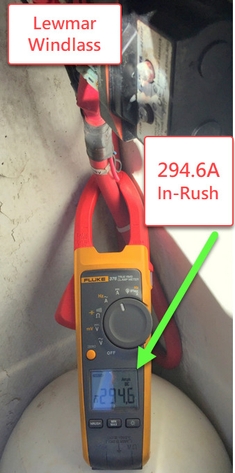
The image above is a prime example of how drop-in battery bank went wrong for this customer. he wanted to lighten the load in the bow of his sailboat so he installed a single drop-in battery to power his windlass.What he failed to understand was the BMS’s current handling rating . In just a few short weeks he destroyed his drop-in battery with his windlass when he failed to account for what the peak in-rush current handling of the BMS., Warranty? Not covered!
1) Balance current-The sealed internal BMS’s in most drop-in batteries don’t have a lot of balance current to work with, usually mA level currents for balancing. We have even seen some BMS specs suggesting they can only balance the cells at a maximum 10 – 30mA or just 0.010A to 0.03A.If you’re running a 200 or 300Ah @12V battery the cells had better be well matched or the BMS may not be able to keep up….Again, Only buy from reputable Vendors!
2) Balancing –Balancing Does not usually start until the cells are exceeding 13.8V or 3.45V per cell. Some are slightly higher and some slightly lower, just depends upon what you bought. Where the cells begin balancing MUST always be specified! If you don’t see this spec ask the manufacturer.. This means that in order to ensure the cells stay in balance they need to get to a balance level at each 100% SoC charge cycle. The reason drop-in makers suggest such high voltages is because balancing is typically done at the top-of charge with a FET based BMS. KiloVault batteries begin to balance at 14.0V(pack) or 3.5VPC.This is is excellent for cell longevity and is why Kilovault (Top-Band) can claim 5000 cycles @ 80% DoD….
3) Absorption Duration –The manufacturers, for obvious reasons, want a short absorption voltage duration, some as short as just 20 minutes but many demand less than 30 minutes. With mA level balancing current, twenty minutes is not a lot of time to re-balance cells so they depend upon the battery getting to the balance voltage with each excursion to 100% SoC. If it does not get to a balancing voltage, the battery cells can become out of balance and the FET BMS may never be able to catch up with out of balance cells..
LFP Warranties
LFP warranties = lawyer-Speak/marketing
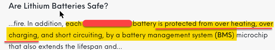
“Each XXXXX brand Battery is Protected from over-heating, over charging…”
Warranty exclusion reality:
CONSIDER YOURSELF CONFUSED!!
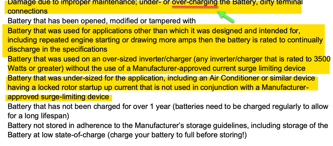 Exclusion: “Damage due to over-charging”
vs. the Marketing ;
“Each XXXXX brand Battery is Protected from over-heating, over charging…”If you’re wondering how a battery that has a BMS that “protects from over-charging Can be “over-charged“?Me too…
Will a Manufacturer be around to honor a 5+ year warranty?
The two brands below no longer exist…..
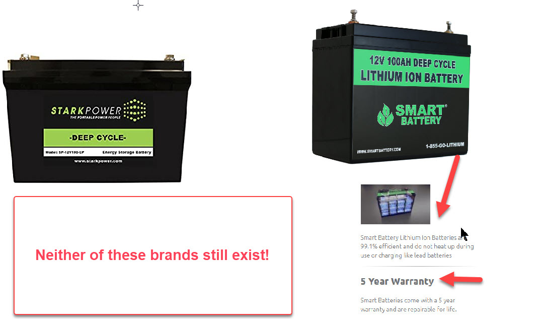
Have you done enough research on a manufacturer?
Could this be a reason why one of the brands from above disappeared?
WHAT ABOUT FLOAT CHARGING
Float charging is a relic that’s left over from lead acid battery charging. Lead acid batteries directly benefit from being held at 100% SoC. LFP do not benefit from this.. Float charging is not necessary for lithium iron phosphate batteries. The only reason any lithium ion phosphate battery manufacturer even suggest a float voltage is to satisfy end users who want to continue using legacy/antiquated lead-acid charging equipment . In no way does float charging benefit your LFP batteries. The act of holding LFP batteries at or near 100% SOC can only serve to slowly eat away at cycle-life. An LFP cell can achieve 100% SOC at just a bit over 3.4 VPC (13.6Vpack voltage) if you’re battery manufacture suggests anything over 13.6V for float you may want to reconsider that and set it below 13.6V .You can always set it lower but should not go higher. I use 13.5V for 12V batts.
When LFP used to cost $10,000.00 to buy & install maximizing cycle life was a huge concern. Today with LFP pricing far lower lower than flooded deep-cycle batteries so, who cares if you loose a few cycles due to floating…
There are charger manufacturers out there who actually understand charging LFP batteries. Victron is about the best known. Victron has a specific setting in their custom menu that allows you to set a “storage” voltage this is a voltage the charger drops to after a short float has been done. It can be custom programmed to allow the batteries to self discharge down to about 50% SoC before the charger kicks back in and maintains the “storage voltage.”the only chargers or inverter/chargers we currently recommend for lithium iron phosphate batteries are Victron.
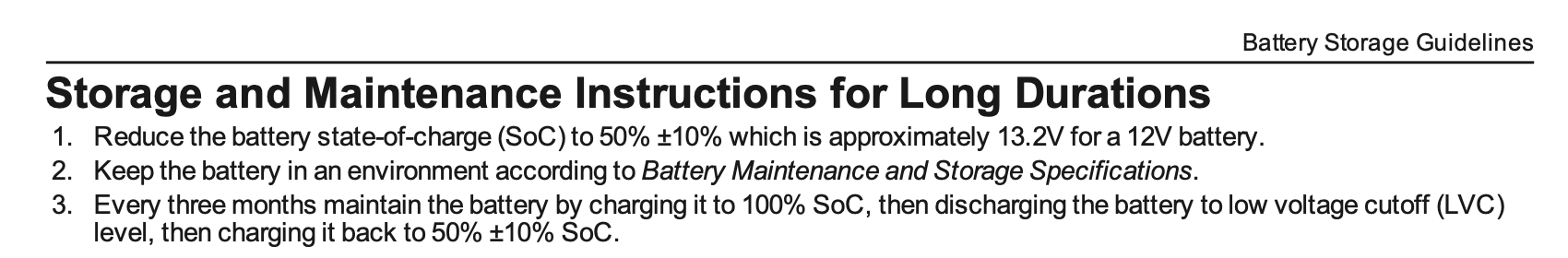
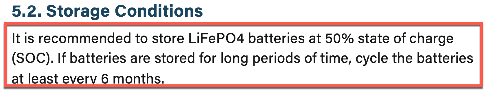
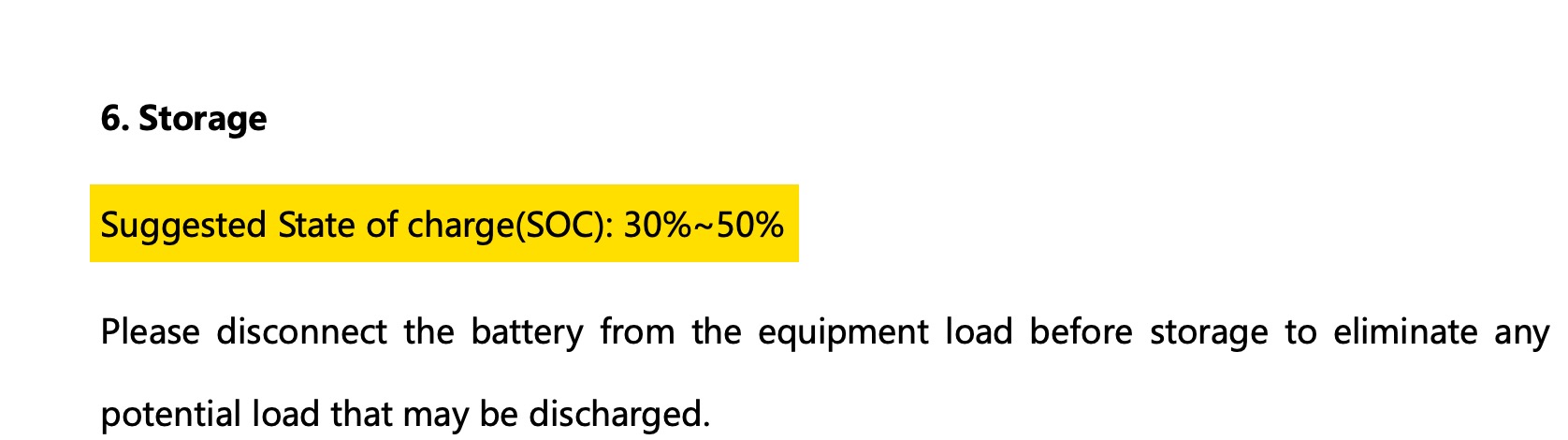
What About Storage?
As mentioned above lithium ion phosphate batteries do not prefer to be sitting at or near 100% state of charge for long periods of time. This is why you will see, from nearly every single legitimate drop-in battery manufacturer, a recommendation for storing the batteries at or near 50% state of charge or less
Below are snapshots from lithium ion phosphate drop-in battery manuals or specification sheets .

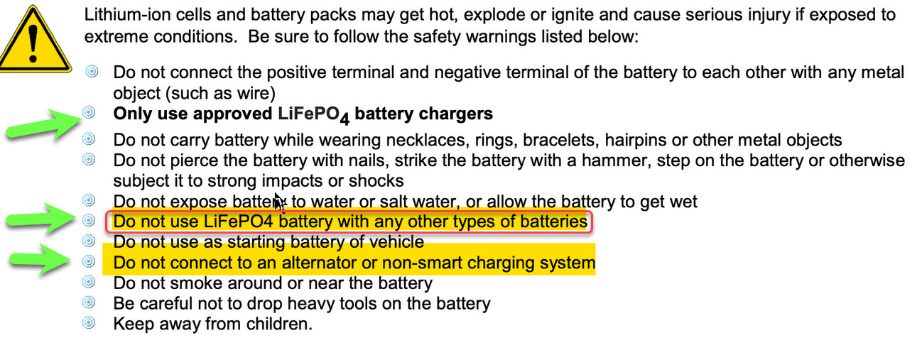
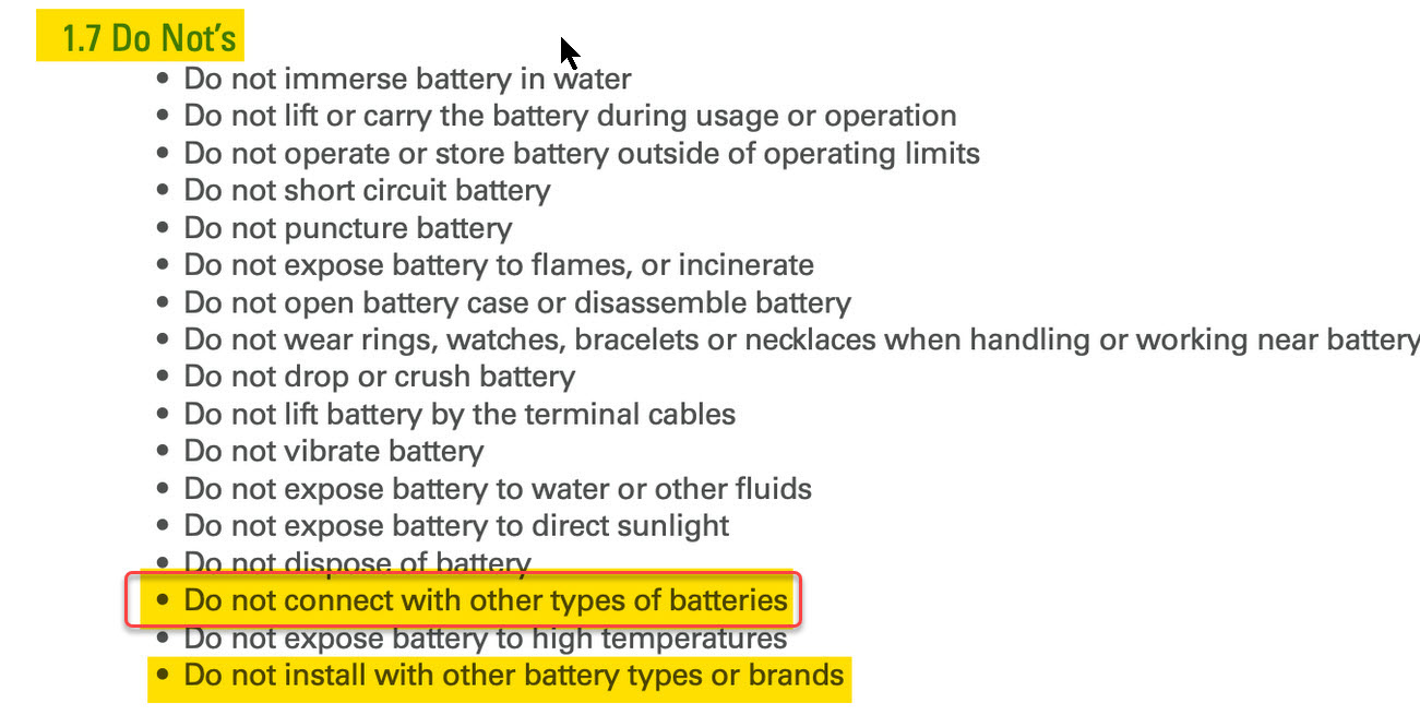
What about “Hybrid ” Systems?
A hybrid system is where an owner decides to parallel Lead-Acid and LFP. Sure, you can find someone on YouTube to tell you what you want to hear, but this is not always what you should hear… Ask yourself what happens when the lead acid battery internally shorts if it is connected in parallel to LFP? ABYC does not prohibit hybrid systems but many batt manufacturers do and ABYC defaults to the OEM.
From LFP Manuals/spec Sheets

Over-Current Protection?
Battery Banks & Over-Current Protection Article
The article above goes into great detail on this subject.Lithium iron phosphate batteries can throw a ton of current into a short but the fuse protecting the wire must have a suitable AIC rating. AIC stands for amperage interrupt current. AIC is different than the fuses trip rating. AIC is the maximum safe-current the fuse or breaker can trip under without having an unsafe-failure. For example if a battery has too much amperage, in a dead short ,Circuit breakers can actually weld-shut before they can trip. This is why AIC matters. The bottom line is that class T fuses are what should typically be used when protecting lithium iron phosphate batteries.Here at CMI we shorted a single 2oAh LFP cell and it easily exceeded 1000A! Now imagine a 400+Ah bank.
ABYC E-13

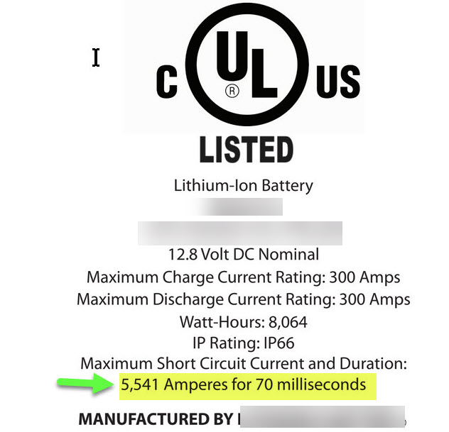
The UL image below depicts a drop-in battery with a FET BMS that is “short circuit protected“. As can be seen this single drop-in battery can still deliver over 5500A into a dead short! Now imagine if you have two or three of these batteries in parallel or four+. The short circuit current of a FET BMS is always considerably higher than one would assume it is When in doubt use Class T fuses for LFP.
A BMS is not considered Over-current Protection Under Any Safety standards
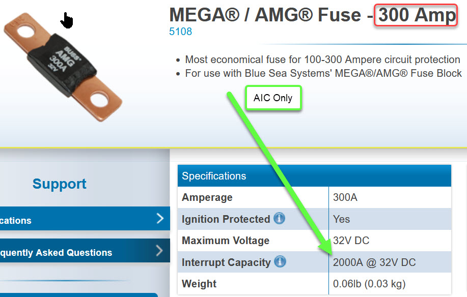
The reason I’m showing an image of the mega or AMG fuse below is because of the growing popularity of the Victron Lynx distribution systems. These are excellent systems, we love them,however, caution must be used when connecting them directly to a battery bank. In North America over-current protection needs to follow the ABYC’s AIC guidance. Mega/AMG fuses are fine so long as they are downstream of A fuse or breaker that is properly AIC rated to handle the batteries short-circuit current. In other words, MEGA/AMG fuses should not be used to directly connect to a lithium iron phosphate as the primary over-current protection as the can only interrupt up to 2000A safely..
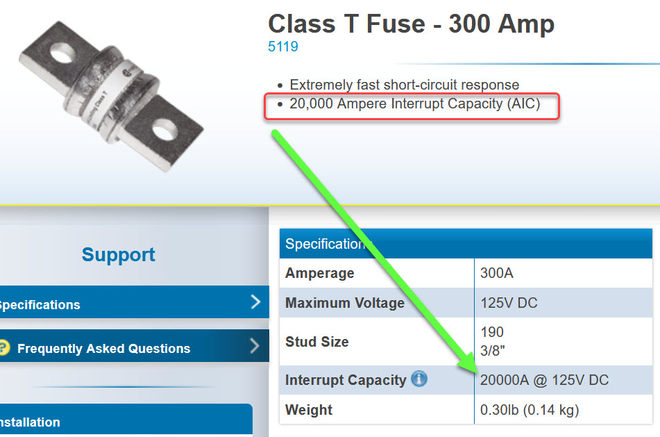
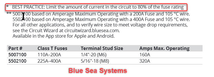
Below are the specifications for a blue Sea systems Cass T fuse. Notice the fully encased metal body and the 20,000 A interrupt capacity. Also note that these fuses are rated at 20,000A at 125 V. Tthe higher the voltage the tougher it is to meet in AIC rating. Compare this to a typical ANL fuse which only has a 6000 amp AIC rating at 32V. a class T fuse would have a significantly higher AIC rating@12 V if it was tested at this point because it meets 20,000 AIC it 125 V there was no sense in spending the money to tested at a lower voltage.
I would be sloppy if I failed to mention that any installed fuse should not be sized to carry more than 80% of its rating. This also goes for circuit breakers. This is especially true when installing inverters & charge equipment and especially alternators. For alternators a fuse of at least 140% of the alternators rating should be used. Thankfully , Blue Sea Systems is finally addressing this and putting it in their literature.
In summary, do your homework, purchase carefully, avoid direct from China imports when you can,install your system safely, use good quality charge equipment and you will be happy for many, many years and thousands of cycles.
Good luck and happy boating!
PLEASE HELP!
This site is 100% reader supported. My wife is urging me to shut it down as it just keeps costing us money. My stroke recovery is very costly as is authoring this site and keeping it secure.
Click the DONATE button below if you would like to make a donation via BUY ME A COFFEE.
