Originally Published March 9, 2004
Disconnect the Coupling From the Transmission
![]()
Day One:
1- Loosen the packing gland nut.
2- Loosen and remove the four nuts between the transmission and coupling.
3- Push the shaft towards the stern separating it from the transmission.
4- Apply a penetrating oil to the shaft and coupling. Use a product such as Kroil, PB Blaster, Thrust or other quality penetrating oils. Do not use WD40 it is not true penetrating oil. PB Blaster or Kroil are excellent penetrating oils. Apply to both the prop end of the coupling and the transmission end by sliding the shaft towards the stern tube.
5- Align the shaft coupling upright and remove the seizing wire and bolt or bolts that lock the coupling to the shaft. Fill the two bolt holes with PB Blaster, wait a few minutes for it to absorb into the holes and repeat a few times. By hitting both ends of the coupling, and the center where the holes are, with PB Blaster, you will get better penetration than just wetting the prop end of the coupling. It’s best to fill the cap with PB Blaster & then use a Q-tip or use an eye dropper for application.
Coupling Removal
Coupling Removal Precautions
IMPORTANT: Unless your shaft is very new, this one was just a few months old, DO NOT used the method shown below.
The connection between your shaft and coupling is a “light press fit” or what is often referred to as an “interference fit”. When you remove a coupling, from a used shaft, the layer of rust that breaks free almost always means your coupling will no longer fit your shaft correctly. Having done in-excess of 100 shafting jobs, on all types of boats, I can say that the vast majority of couplings, well over 90%, cannot be safely re-used once removed. Re-using a coupling that does not fit correctly is a boat sinking safety issue! The majority of the time you will save money by cutting the shaft and replacing it with a new shaft and coupling.
I hate to even show or share the method used below but, in rare instances, it can work. There are shaft couplings, typically very new ones or ones in fresh water, that can be removed this way, if you are very, very careful.
Please be aware that it’s very easy to bend a gear box output flange. If you do this by using the method shown below it will make future alignments impossible. To remove the gear box, and replace the output shaft, will run you much more money than buying a new shaft and coupling that’s already been fitted & Faced.
Safer Coupling Removal Options
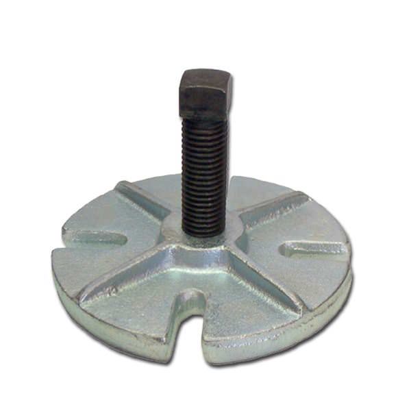
A better method is to have a metal pressing-plate made for you at a machine shop or just get a small scrap of steel and make it yourself. Have the plate made with the same bolt pattern as your coupling and then use it to press the coupling off with a socket, smaller tghan the shaft OD, PLACED in-between the two. The pressing-plate takes the risk off of the gear box flange and places it squarely on an easily replaced shaft coupling and your make-shift pressing-plate.
Buck Algonquin (see below) also makes a flange puller that works well, however you’ll need good clearance between shaft coupling and gear flange for the Buck Algonquin flange press tool to fit in-between. We own one of these tools but it is often useless on many sailboats and smaller in-board boats because the builder has simply not left you enough room.
Test the fit before re-installing the flange!
If using any coupling removal method it will be imperative that you take both the coupling and the shaft to a machine shop and have it tested for both fit and run out. You would then have a shafting shop or machine shop perform a fit & face before re-installation.
It takes very, very little force on these couplings to throw them out of true. Bend a coupling or gear flange out of true and you’ll induce what is called shaft-whip and you will now have a boat that is physically impossible to align. Do not cut this corner, and do not over tighten the draw-bolts, if attepting to remove the coupling by using the gear box flange.
This coupling came off easy compared to many. Still, when I took it to the machine shop it was out by 7 thousandths. Lucky the gear box flange still spun true. I suspect this shaft came from the factory with an improper fit & face, which is not an uncommon corner for boat builders to cut.. It lacked any evidence or signs of ever being faced. This would have made for an impossible alignment and certainly explained the vibration on this brand new vessel.
Safest Coupling Removal Option:
The safest option for your gear flange is to simply cut the shaft and replace the shaft and coupling. On many boats this is really the only option due to rust, corrosion or space constraints.
The process if the coupling is quite new:
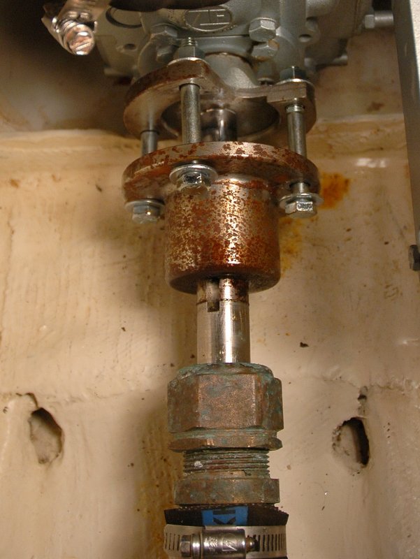
1- Insert a deep drive socket that is slightly smaller than the shaft size between the center of the shaft and center of the transmission hub. See the picture below for a close up of the socket between the coupling and the transmission hub.
2- Insert four long threaded bolts, preferably without shoulders (the part on longer bolts with no threads). This boat was only two months old and the coupling was not that tough to get off but it had already begun to rust on. Luckily the layer of rust was not enough to disturb the fit. Other boats where I know they are rusted on I would use fine threaded bolts and a custom made pressing plate or my Buck Algonquin tool. I usually avoid the gear box flange unless I know the flange is not or very minimally rusted. Be sure to use washers between the coupling and transmission hub and begin tightening EVENLY.
3- After some initial tightening, and with the bolt pressure still on the shaft and coupling, you may need to go outside the boat and tap the prop shaft towards the bow, yes the bow, with a wood or lead mallet. Remember this is NOT a driving blow more of a tap. This is not a pounding with the mallet, just a light strike. If you hit it too hard you can brinell/dimple the bearings and or races in the gear box and ruin them. Once you’ve tapped it climb back inside and a heat gun can be used to warm and expand the coupling. Do not use a torch with the PB Blaster. A heat gun will work wonders. Heat and rotate, heat and rotate etc. etc..
WARNING: Please DO NOT over-tighten the bolts. If it does not want to come off please STOP. Pushing this any further will damage your gear box. Remember it takes very little force to throw the gear flanges out of true.
NOTE: Use a scrap piece of maple between the mallet and the shaft to prevent potential damage to the end of the shaft from the hammer if you don’t have a soft metal or wood mallet.
4- After the machine shop visit, for a fit & face check, bring the coupling home to clean and paint it with a rust proof paint.
WARNING: Be very careful not to get PB Blaster or Kroil near any engine or transmission seals. True penetrating oils will eat engine seals causing catastrophic failure of that seal. The most common seal that I see destroyed is the transmission output shaft seal. Be very, very careful using PB Blaster on your engines coupling bolts. Avoid using the spray nozzle feature when working that close to seals. If you need to use a penetrating oil, on a coupling or bolts, fill the PB Blaster cap with the penetrating oil and then use a Q-Tip to dab PB Blaster on the bolts being very careful not to drip any penetrating oil on or near the transmission output shaft seal.
DON’T BE THIS GUY!!
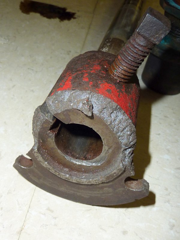
Please do not over tighten the draw bolts. This boater was very lucky he broke the shaft flange and not the gear box flange. Despite his gear box flange not physically breaking, it was now severely out of true. The only way to fix the bent gear flange was to do a gear box tear down & rebuild.
Despite the gear box output flange not breaking, it still cost $1750.00 to fix the bent gear box output flange. Remember these flanges are going to be aligned to 0.003″. It does not take a lot of force to bend the output flange by 0.003″.
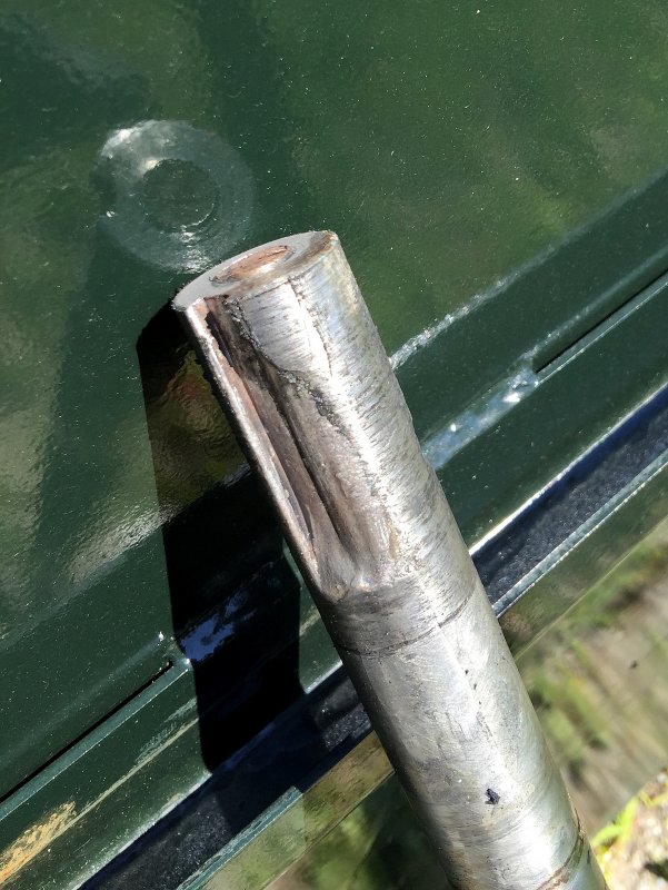
If the coupling does not come off fairly easily you can cut the coupling just over the key way as seen in this photo. Creating the cut at the key way will ensure that you don’t damage the shaft. Once cut it will relieve the pressure and the coupling will then come off.
IMPORTANT: Cutting a coupling this way takes tremendous patience and will cover the interior of your vessel with iron/steel dust. Once moist/humid air sets in it will turn everything it landed on into a rusty looking mess. The better option is to simply cut the non-ferrous brass or stainless shaft.
If you can’t get an angle grinder in there to cut the coupling you will likely need to cut the shaft. Not all couplings will come off so PLEASE don’t ruin your transmission in the process.
The Coupling Has Started To Move
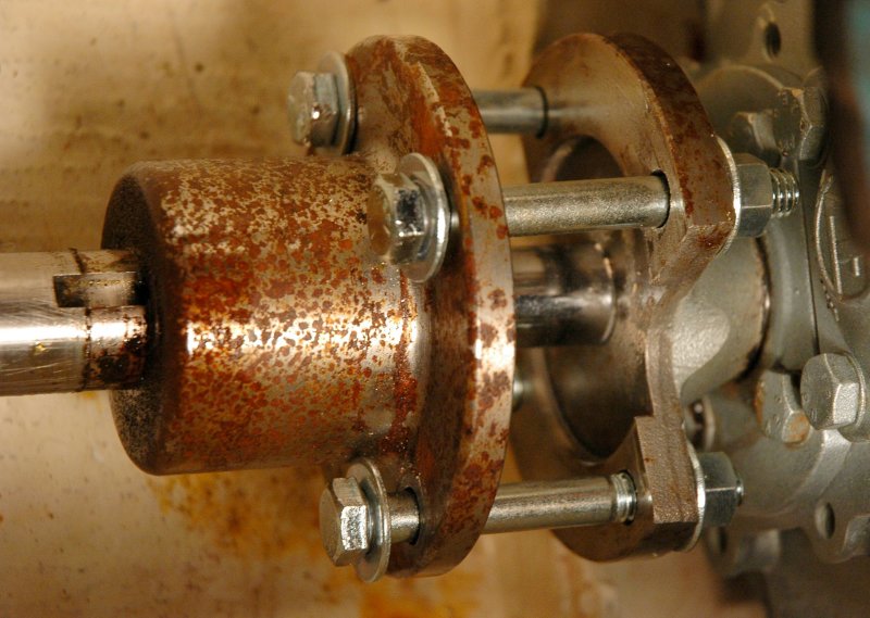
Here’s the effect, and penetration, of the PB Blaster penetrating oil. The coupling has broken free and is beginning to come off through the slow and even tightening of the bolts. Keep in mind this boat was only a couple of months old and this coupling was barely re-usable due to the light layer of rust that broke free.
If you have trouble getting the shaft and coupling apart you can heat the center of the coupling very slightly with a heat gun (make sure you have an extinguisher on hand just in case) heating it in the CENTER will allow the PB Blaster to flow into the coupling.
What Can Happen When you Re-Use a Coupling

Remember when I mentioned using a machine shop to check the fit & face of a coupling you removed? Well here’s what can happen when the fit of the coupling is too sloppy from a removal and re-installation.
A straight-fit-coupling, what most sailboat shaft couplings are, is supposed to be a light interference fit. Removing a rusted coupling, and breaking that rust layer free, can destroy this very, very narrow window of precision fit.
Click on this image and look closely at the key. It should not look like this. This was caused by a removed coupling being reinstalled with a poor fit. Reinstalling a used coupling, without checking for a proper interference fit to the shaft, can be very dangerous.
Another Improperly Reinstalled Coupling
This DIY had actually taken the time to read this article. Sadly for him, he chose to ignore the advice on properly fitting couplings. He re-used the old one. He did this in order to save approximately $80.00. In the end it cost many thousands in repairs and an insurance claim that wound up getting him cancelled the nest year. His insurance premium is now more than double what it had been. Lets see, spend $80.00 now or $26,000.00 a few weeks later? I call that penny-wise, pound foolish.
Tow to Boat Yard $$$
Haul Out – $$$$
Short Term Storage -$$$$
Labor to Drop Rudder -$$$$
New Shaft & Coupling – $$$$
Prop Repair (prop hit hull & rudder) – $$$
Strut Repair – $$$$
Water Damage Repairs – $$$$$$$ (boat was sinking when shaft backed out)
Rudder Repair $$$ – (prop hit rudder when it backed out of the boat)
Transmission Repair – $$$$
Losing of 85% of the 2015 Boating Season = Priceless
Please let the seriousness of cutting corners, when removing a coupling, sink in!!!
Often Times It is Best Just to Cut It Out

Often times the best course of action, or the only course of action, can be to just cut the old shaft out. This becomes especially true if you are paying for the labor. The shaft on this boat was 23 years old, had severe cutlass bearing wear and also really bad stuffing box wear. The coupling was so rusted, and space so limited, that the safest and most reasonably cost effective option was to cut it out and have a new shaft made.
Doing this ensures that you will not harm your gear box and you know you are starting with a new fitted & faced shaft & coupling that has no wear and is straight.
Slide Hammer Warning
WARNING: Never, let a boat yard use a SLIDE HAMMER to remove your coupling. NEVER! The use of these short-cut processes can destroy and brinell the bearings or races in your gear box. I’ve witnessed yard guys hit them so hard, with a slide hammer, they’ve actually spit a gear box case in half. Cut the shaft or cut the coupling off before you allow anyone to use a slide-hammer. A shaft or coupling is far less costly than a destroyed marine gear box.
Brinelling
In this image, of very light brinelling, you can see vertical lines in the bearing race. These are actually what the flat spots, created by slide-hammer, look like. It can be much worse than this too. In this example of light brinelling can see why the gear often does not fail immediately and why you cannot usually lay blame on the boat yard. These flat spots however will eventually lead to a failure and you’ll be on your own to re-build the gear box.

If your yard insists; “We do this all the time, it’s no big deal.” it’s probably time for you to find a new boat yard. Sorry to be blunt but this practice is simply horrifying.
Why do boat yards continue to use slide hammers?
1- They know the brinelling of the bearings/races damage (brinelling creates flat spots in the bearings or races) will not rear its head immediately and thus the damage is not likely to be blamed on their use of the slide hammer.
2- They know it will result in future repairs.
3- They simply do not care about you or your property.
4- They are simply uneducated about what can actually result from the use of a slide hammer.
Just say NO to slide hammers!
Almost Done

In this photo you can see that I have painted the coupling after getting it back from the machine shop, and am in the process of fitting everything back into place.
Beating the Dead Horse / Shaft Coupling Must “fit” Correctly
1- The best rule of thumb, when removing a coupling, is to always take the shaft and coupling to a shafting/machine shop for a fit & face check before re-installation.
The shafting shop I use fits the coupling to the shaft with a light interference fit. A light interference fit means it does not just slide onto the shaft at room temperature. Western Branch Metals, the largest supplier of prop shafting in the US, suggests that the shaft OD be about 0.0003″ – 0.0005″ larger than the ID of the coupling. If you understand what this means it is simple to see that with a proper fit it will require some light tapping to get the shaft & coupling together. Alternatively some heat, no more than about 200F, to get the coupling to expand and slide over the shaft.
A “clearance-fit“, where the coupling just slides on is 150% unacceptable for a straight or even a split coupling. It can cause excessive shaft, key and coupling wear and can eventually lead to a shafting fracture or failure. The coupling needs to be an interference fit.
2- The shaft, such as Aqualoy, Aquamet or Nitronic (all stainless variants) is more often in re-usable shape and can often be cleaned up and re-used. It’s the steel coupling that gives up its surface material, not the shafting. This lost layer of rust means you can’t usually re-use it. If a coupling just slides back on it is an improper and unsafe fit.
3- When reinstalling a new coupling, to an old shaft, you should always have it fitted & faced by a competent machine shop or prop shop. Shops generally charge around $65.00+/- for a fit & face. While you are at it have the shaft checked for true. Shaft truing is more costly than a just a fit and face but generally cheaper than a new shaft and it will help to minimize any annoying vibrations. Another good practice to minimize vibrations is to lap fit the prop to the shaft, and you can actually do this yourself.
If you hit something and bend the tapered end of the shaft, near the prop, the shaft is often considered ruined and most any reputable shop will not straighten it, but let them make that diagnosis.
4- When re-installing the shaft you should get it started with the machined in “lead” then lightly tap it home with either a rubber mallet, soft lead mallet or an oak or maple block protecting the shaft, and a hammer. Alternatively you can cool the shaft and warm the coupling. I am not talking blow torch here just warming one and cooling the other. For this job you’ll usually need two people or many trips up and down the ladder. Tap it in while looking in the coupling holes until you see the dimples for the set screws. I color the spotting in the shaft with a red sharpie marker then use a flash light to see when they dimples or spots are lined up. Don’t over do it because backing it off is more of a pain than driving it in.
5- Shaft keys should fit tight in the shaft, I call this tap-fit snug. The coupling fit should be snug but not binding. If the key has any play/slop in either the shaft or coupling have a machine shop make you a new one.
6- Anti-corrosives like Tef-Gel can sometimes aid in future removal but it’s no guarantee and is generally advised against. You should also not use a never-seize product containing any aluminum, copper or graphite as it can add to galvanic corrosion issues.
I have been experimenting with Tef-Gel and had good to mixed results up to about two years with coupling removal. It does aid some in the removal but does not always mean the coupling is re-usable. It is not recommended to use any lubricant between the coupling and shaft so do so at your own risk. I do not advise this, despite my experimenting.
7- If you can, don’t replace the coupling with a solid coupling and instead replace it with what’s called a split-coupling. This will make future removal and re-install much easier. Even with a split coupling you should still have it fitted and faced after removal. The $65.00 +/- is well worth it. Split couplings require the utmost care in installation. The nuts should be tightened EVENLY and to proper torque. Uneven tightening of the clamping nuts can cause a split coupling to be thrown off in true. Tighten each one a little at a time.
8- Once again do not use a large hammer, or a slide hammer, with any great force, to pound or pull directly on a coupling that is connected to the transmission. You can rather easily damage the bearings and brinell them. Brinelling of the bearing surface creates an imprint of the roller bearing on the face of the bearings race. Brinelling of the race, or bearing surface, will eventually lead to a bearing failure and gear box re-build. In extreme cases the gear box may shatter and there are many out there who have done just that. Slide hammers should be avoided at all costs.
PSS Seal Cut-A-Way
This is a cut-a-way view of the PSS Shaft Seal. It’s critically important that TWO set screws be used as shown. This means one set screw on top of the other, in order to lock them into place. The o-rings should seat in the slots well and no grease or oil should be used when sliding the rotor onto the shaft.
The factory PSS set screws ship from the factory with thread locker already applied. It’s the off white/yellowish stuff you can see on the set screw threads.
Set Screws = One-Time Use
The set screws are a critical component of the PSS system. You should always use two set screws in each rotor hole. The top one is used to lock the bottom one into place and prevent it from accidentally backing out.
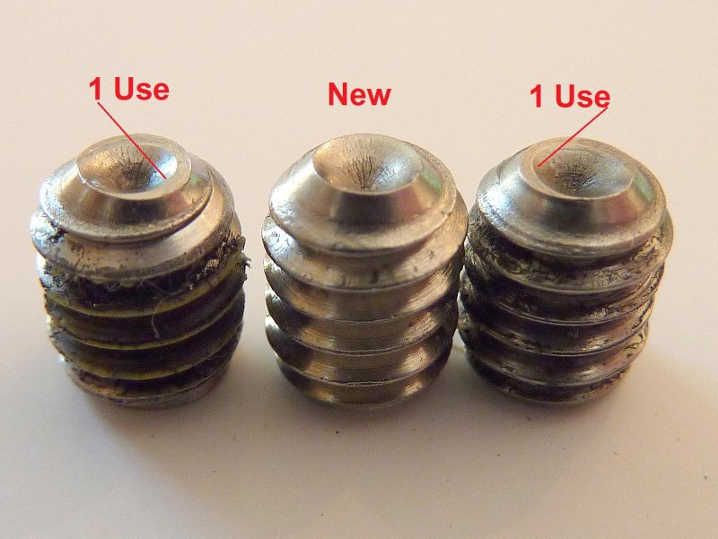
Set screws are a one-time use:
What is a one-time use? If you tighten the set screw to torque, even once, that is your use. For example if you are installing the PSS and adjust it, tighten the set screw, then realize the adjustment was incorrect, you now need to use a new set screw. If you look closely you can see how the used screws flatten. Once flattened they will not score/bite into the shaft, like when new and sharp, to properly lock the rotor in place.
If you’re in an absolute emergency you can simply swap the screw that had been the top locking screw for the bottom one. I still don’t advise this a regular practice. PYI recommends using new set screws with each tightening and loosening of the set screws.
PYI is glad to ship them out to you for a very minimal charge. Please, for your own good, avoid the re-use of set screws.
Clamp-Collar = Insurance Policy
What is a clamp-collar? It’s cheap Insurance against the PSS stainless rotor moving. Yes, I admit that I’m one of those cautious individuals who will walk through potential failure scenarios to make a final installation as safe as can be. I discovered stainless steel clamp-collars late one night on the McMaster-Carr web site and ordered one just for this purpose.
I place the clamp-collar right behind the rotor and lock it into place. I have been using them now for 19+/- years and consider them a very, very reasonably priced fail safe or insurance policy, which goes above and beyond the set screws that were just discussed.
EDIT: PSS apparently saw this idea and decided it was worth launching their own PYI clamp-collar. According to an inside source at PYI they are reported to hold over 1000 pounds of force on a 1″ shaft. That, is indeed very good insurance beyond the set screws. At last check the PSS/PYI clamp-collar was less costly than the collars I buy from McMaster-Carr, though I have not confirmed if they are 304SS or 316SS.
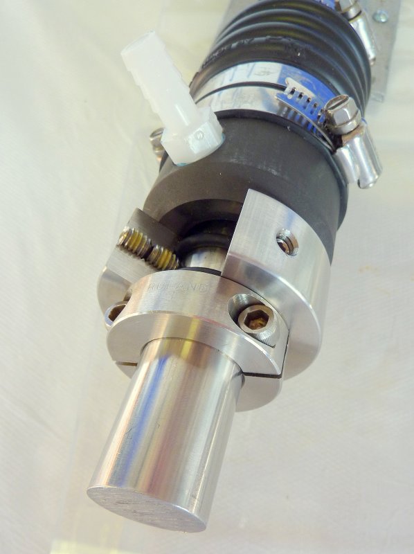
Clamp-Collar Installed
This is a photo of the clamp-collar in use on a v-drive installation.
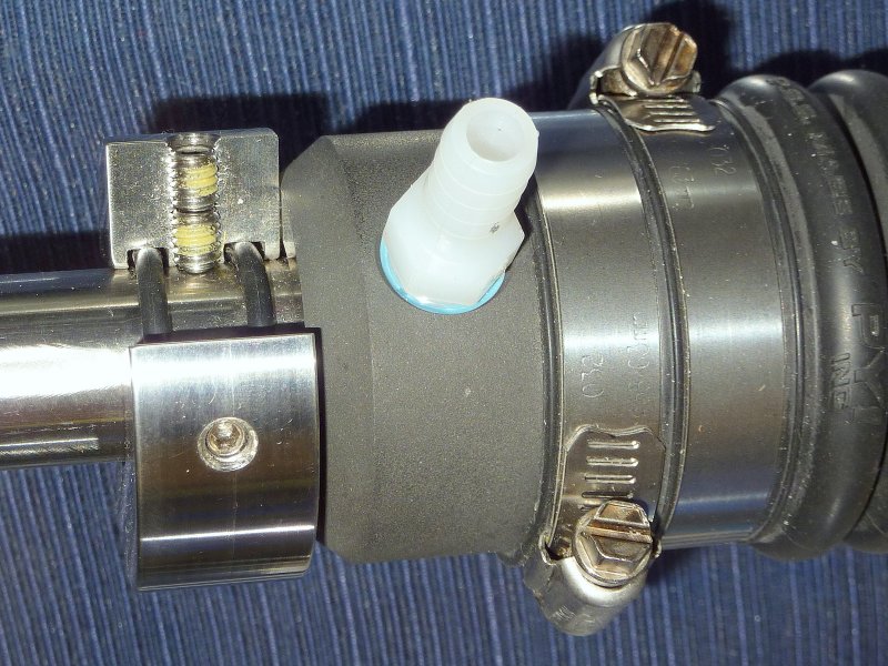
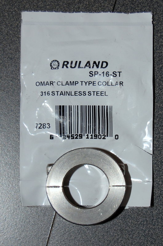
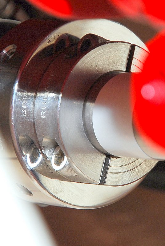
The Ruland Clamp-Collar
Here’s a better view of a Ruland clamp collar that can be purchased from Mcmaster-Carr. I brought this one to a friends shop, where he has a PSS display, in order to show more accurately how it is installed.
PSS Shaft Seal – With Painted Coupling
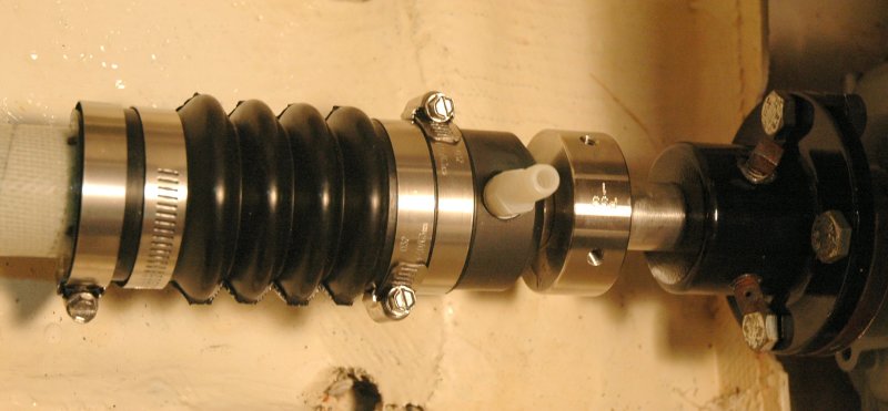
This is the order in which the PSS Seal goes together.
PSS After One Seasons Use
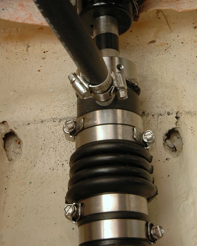
After an entire season all you’ll to show for this installation is a tiny carbon/graphite line, which is barely visible. This line is left over from the break in process. It results from the rotor face and carbon block smoothing each other out.
Notice that everything below the water line is double clamped.
IMPORTANT: As a corrosion specialist as well as marine electrician I have noted for many years increases in anode erosion once a PSS seal is installed. This is nothing to be alarmed about and is pretty normal. Graphite is at the top of the galvanic scale and the rotor is made from graphite & carbon. This increase the voltage spread between the most noble, the PSS carbon block, and the most anodic metal, your anode. It just means the anode needs to work a bit harder and may erode a bit faster. If in doubt consult a marine corrosion specialist.
Vent Hose Routing

To get the vent hose above the waterline and into the engine compartment put a smooth bend with enough slack for flex and then route the hose into the engine compartment. Make sure it does not chafe on anything along the way.
Vent Hose Water Collection Bottle
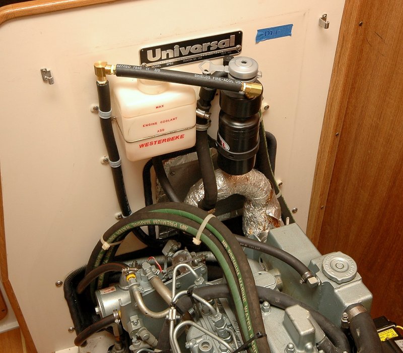
The PSS vent hose is critical and intended to keep the seal faces lubricated but allowing any entrapped air to vent out of the shaft log. By venting it into the vessel you may find the vent burps when you place the boat in reverse. The reverse thrust of the prop is in a direct line of sight with the shaft seal and can force an initial burp of water up and out of the hose. The water does not continuously squirt out, and it equalizes quickly, but an initial thrust, of reverse, can push about an 1 oz of water up the tube and into the boat.
To solve this problem I’ve added, to the existing vent hose, a couple of brass elbows and a bicycle water bottle and bottle holding bracket to catch this reverse thrust water. To make sure the system was still able to vent air I made a hole in the top of the bottle to facilitate venting and routed the vent hose into the bottle below this hole. It takes about a two-four weeks of using the boat before bottle tends to get full. Just check on it when you check the oil. If you are venting a PSS internally be aware that running the engine in reverse can and will push water back into the boat..
Water Collection bottle Vent Hose Fitting
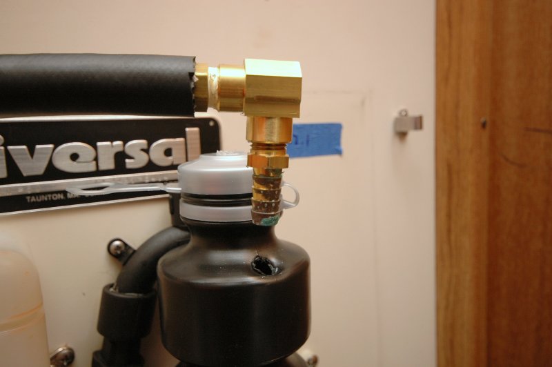
PSS Shaft Seals are all vented so no air can become trapped in the shaft log. An air-bound shaft log can result in the PSS running dry and becoming extremely hot. If the shaft log becomes air entrapped the rotor faces lack lubrication and the PSS is a water lubricated shaft seal.
Despite many rumors and mistruths about slow turning shafts not needing to be plumbed or vented the reality is that even slow turning shaft vessels can develop entrapped air up in the shaft log. The vented or plumbed hose keeps the seal faces lubricated by venting or displacing the air and allowing water to take its place. The problem is this hose needs to be routed above the waterline with no low spots. Low spots trap water, like the p-trap under your sink, and thus preventing the venting of entrapped air.
In this Catalina 310 it was dificult to find a route that would not have a low spot where water could become trapped. The engine compartment route was the only way I found that did not hold water or impeded the flexibility of the vent hose on the shaft seal. Routing into the engine compartment, on this particular boat, solved this problem and the water bottle kept burped salt water off the engine. The hose barb pictured just pressure fits nicely and is easily removed to empty the bottle from reverse thrust burping.
Close Up Of Water Collection Bottle
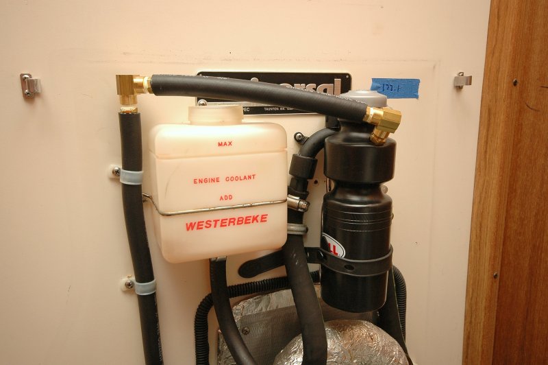
This picture gives you a better idea of what the completed set up looks like. At first I was concerned about heat from the exhaust riser but an infrared thermometer confirmed that the bottle stays plenty cool and besides it fits well.
The blue tape on the back wall is reminding me of the engine hours when I last changed the oil. It’s a crude system but it keeps me on my oil change routine
Hydronic Heating System Hy-Vent® used as the Air Vent

While the water bottle works, I found it to be a less than elegant solution than I was happy with. I decided to use a Taco model 400 Hy-Vent® instead. These are available at most any plumbing supply house.
Please don’t ask for a Taco, as in the Mexican food, the company is pronounced it Tay-Co. The Hy-Vent® I use is a 1/8″ male NPT version and it’s then connected to a hose adapter. I’ve had many these in use for over 15 years now with zero issues. I initially thought I may need to rinse it of salt yearly but that has not been necessary. They have not leaked on me and not trapped any air either. Being that these should be installed well above the static & heeled waterline, and they are empty of salt water 99.98% of the time, they don’t need to be a “marine bronze”. If it were to corrode simply dig into the pocket for about $9.00 and its fixed.
The Taco Hy-Vent® uses a plastic float connected to a Schrader type vale inside the brass body. When the vent is full of water the float closes the Schrader type valve making the system water tight. A reverse burp causes the float to shut the valve. If there is no water present the Schrader valve opens to allow air to vent out of the system. These are simple devices and not very expensive, about $9.00 at a plumbing supply house.
The PSS Shaft Seal is a reliable time proven system that keeps your bilges dry. Every issue I have ever heard of involving a PSS seal involved installation or user error. Follow the instructions, replace the bellows per PYI’s time schedule and the PSS is a reliable work horse.
Good luck and happy boating!