A Fresh New Alternator
For many boat owners the task of upgrading their engines alternator can be intimidating. It does not have to be, and this article will help you understand how to do this job correctly. It includes numerous professional tips & tricks that can save you lots of time and headache up-front, before you even begin. This article could easily be written as this:
- Identify Mount Type
- Identify Pulley Configuration
- Chose Your Alternator and/or Pulley Configuration
- Install Alternator and/or Pulley Kit
- Adjust Belt Tension
- Fire it Up
Clearly the above list is over simplified but that’s it in a nutshell. This article will delve into the nuances and provide you with numerous tips and tricks that will make your installation that much less stressful. Not all of the steps or tips/tricks are necessary with each installation but we have provided them so you have a solid quiver full of arrows at your disposal.
Why are we delving into all this?
Myth: I bought a “drop-in high performance alternator.”
Reality: An alternator upgrade will usually require more than just a “drop-in” installation.
This article deals only with the physical installation of the alternator. See our other articles related to alternators here:
Marinehowto.com Alternator Articles
Site Plug:
MarineHowTo.com is 100% reader supported. Help keep it free.
This is not just another “How-To” article with no real intimate knowledge of what we are writing about. We also build/manufacture our own line of custom marine alternators. Our AMP-IT custom alternators represent a tremendous value. We have no middle-man margins to account for, and sell direct to the end user. The AMP-IT alternators represent a tremendous value in an externally regulated alternator. We will steer you towards Balmar’s products every day of the week but if it is too rich for your blood, a custom built MP-IT alternator may be a better fit. (AMP-IT alternators has been closed due to health reasons.)
MHT recommended alternator products:
Buy Balmar Products
Upgrading Your Alternator
The choice to upgrade your vessels charging system will often include considerations regarding your engines alternator. This is especially true on sailboats where short engine run times are the norm, and the fastest possible charging is the desired outcome. On most stock marine engines the factory supplied alternators are frustratingly inadequate for charging a large heavily depleted house bank of batteries. In almost all cases they are nothing more than an off the shelf internally regulated automotive alternator and simply not designed for extended heavy duty operation charging large banks of batteries..
For more information on the problems associated with stock alternators please read the article below:
AUTOMOTIVE ALTERNATORS VS. DEEP CYCLE BATTERIES
This article assumes you’ve made a decision to upgrade your alternator and now you need to install it. This article will cover aspects of the physical installation including.
- Alternator Choices
- Belt Options
- Alignment & Shimming
- Pulley Types and Considerations
- Pivot Bolts and Adjuster Bolts
- Adjuster Arms
- Best & Worst Practices
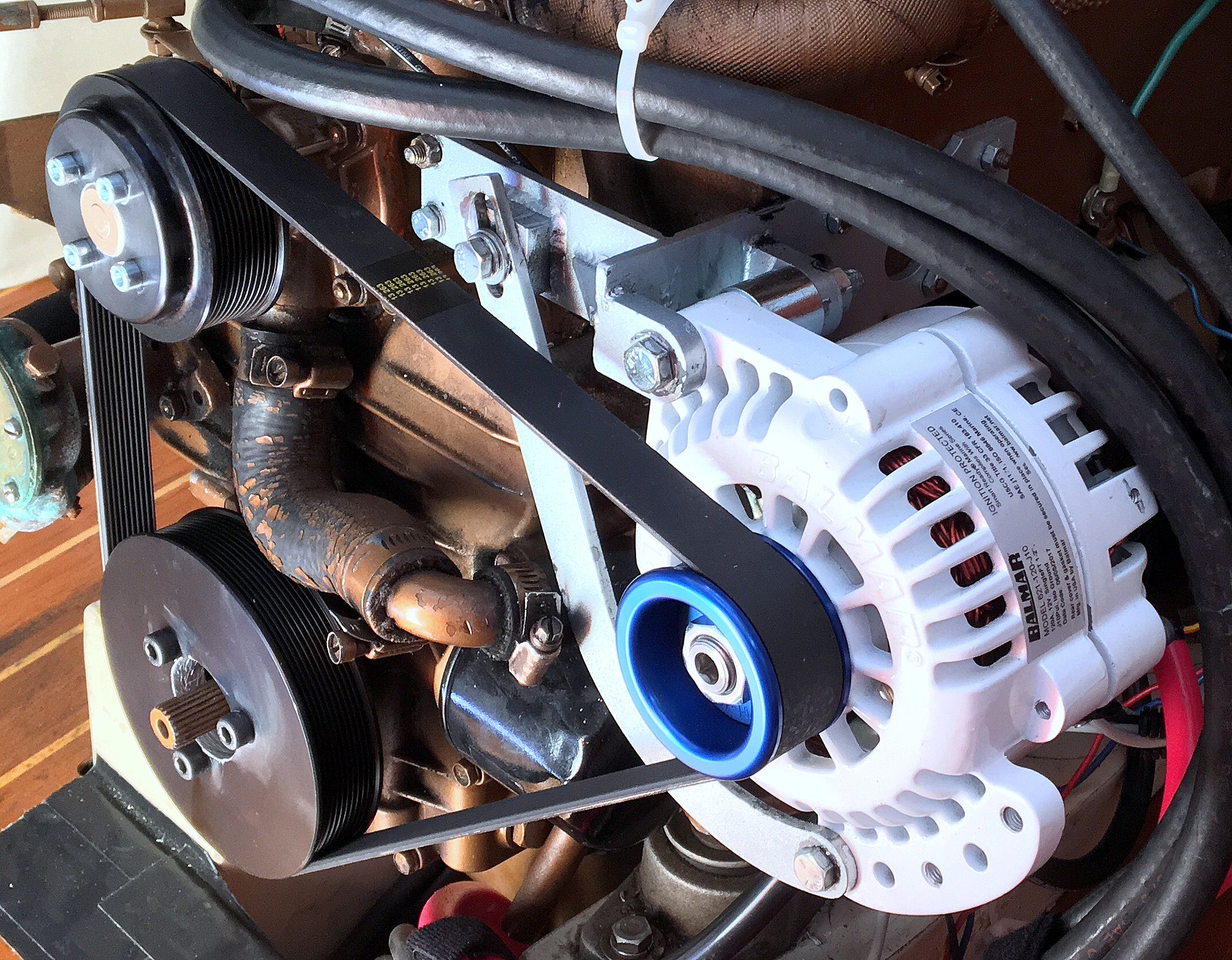
In this image the boat owner has chosen to upgrade his stock, 51A internally regulated alternator, to a 120A small frame Balmar 6-Series and a serpentine pulley kit.
Making Sense of Alternator Frame Sizes & Output Ratings
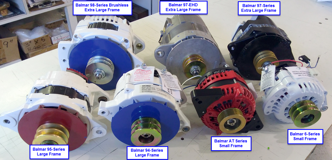
Aftermarket externally regulated higher performance alternators are generally classed into three basic categories – Extra Large Frame, Large Frame or Small Frame.
The differences in case (frame) sizes can be seen here:
Many marine engines, other than some large Cummins, Cats etc., generally ship with what is called a small frame alternator. Small frame alternators run the gamut in terms of build quality and durability but none of them are what could be considered “constant duty“. The only way I know of getting a constant duty small-frame alternator is to remove the internal rectification and rectify remotely. This is what I have done on my own vessel for charging a large LiFePO4 battery bank.
“What does constant duty mean?“
What it means is the small frame alternator you purchased is simply not a “constant duty rating” no matter who’s name is on it. For years and years, with moderately sized banks of deep-cycle flooded batteries, this did not really matter because the batteries came up to voltage pretty quickly and then the alternator caught a break. Today I have customers with 600Ah plus battery banks on 30 footers. This may seem insane by yesterdays standards but not by today’s standards. The growth & use of computers, tablets, TV’s and other iToys over the last ten years has been immense. Today it has many of our customers exceeding the daily energy consumption of their DC refrigeration. Not too long ago DC refrigeration was the huge energy hog today, for many, it is computer, tablet and device use.
Small Frame Marketing Hype
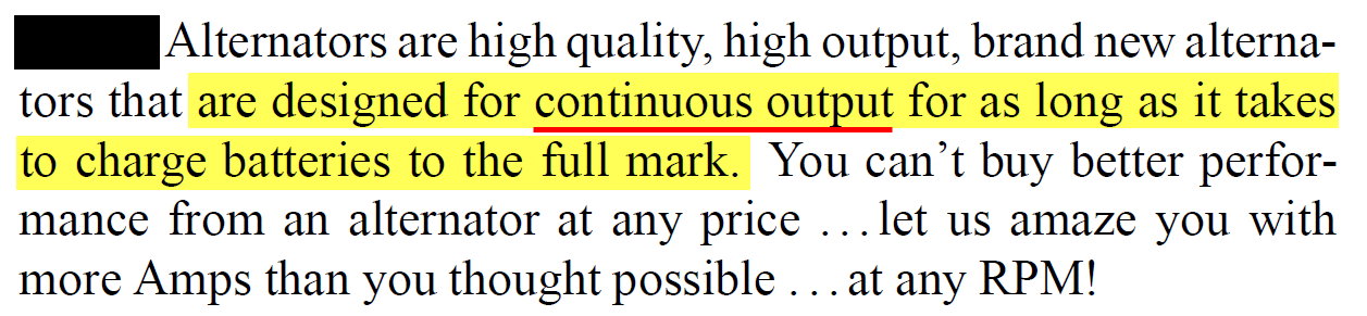
The Real World Reality
The cooked alternator you see below was made by manufacturer of the rather brash statement above. It was marketed in what I would consider to be a grossly misleading manner. This alternator was a small frame, single fan unit and we have seen many of them burned up, from being over-worked while not being adequately temp protected.
Burned up alternators like you see below can happen due to a lack of alternator temp sensing/protection and/or a lack of being able to current limit the alternator. Compass Marine Inc. actually builds the identical alternator using the same internal components from the same manufacturer. We go a few steps further however and build the alternator with 400V 75A diodes. The manufacturer of the misleading claim above used only 200V 50A diodes. Despite the ability of our version to deliver significantly more power, and for longer, we would never, ever tell a customer the Compass Marine Inc., AMP-IT-HD125-ER, is a continuous duty unit. That would be pure unadulterated BS.
This one was charging a large AGM bank,LiFePO4 will tax an alternator even more than AGM, and this was the second identical alternator to suffer the same exact fate. Two separate but identical alternators completely cooked themselves in a matter of months. The pictured alternator was measured at 367F when the owner had noticed his tachometer stopped working. Upon opening the engine bay a thick acrid smoke hit him in the face. The regulator being used on this alternator had no alternator temp sensor and no way to current limit it. The regulator was replaced with a Balmar MC-612, plus an alternator temp sensor, and current limiting or “Amp Manager” was used. The third identical alternator is still running to this day, 9 years later.
There is no small case alternator we know of that can run continuously at full output.
Anyone telling you otherwise is simply a bovine dung artist

“I bought an XXXXXX brand alternator and it has a hot rating?“
Please let’s not misconstrue the difference between a cold rating & hot rating and a “constant duty” rating. A hot rating and a constant duty rating have no relation to each other at all. In the industry alternators are tested to ISO 8854 or SAE J56. These testing standards help standardize output ratings at a certain RPM, temp and test voltage.
Alternators tested to SAE J56 are simply rated like this:
Test Temp = 23ºC ± 5ºC
Test RPM = 6000
Test Voltage = 13.5V
Unfortunately this industry standardized testing is not designed nor intended to see how long the alternator can run at full output into a large bank of deeply discharged batteries. In other words, an alternators output rating is rated cold (73ºF to 83ºF) at 6000 shaft RPM and 13.5V. Simple stuff. While some marine alternator manufacturers, such as Balmar, provide both a cold (79ºF) and a hot rating (194ºF) this hot rating is still not a constant duty rating. The hot rating is simply telling you the expected drop in max achievable output, as the copper in the alternator heats up to 194ºF. A cool alternator simply produces more peak output than one at near 200ºF.
A “Hot Rating” is not a Continuous Output Rating
Why don’t manufacturers supply a constant duty rating? The reason is pretty simple, it’s because every application and engine space is different and providing a continuous rating is nearly impossible to apply across each installation scenario. Below are three examples of measured engine room temps to illustrate why this is not done with small-frame alternators:
Boat #1 Engine Room Temp = 162.4ºF
Boat #2 Engine Room Temp = 171.1ºF
Boat #3 Engine Room Temp = 132.5ºF
The alternator on boat #3 is going to have a much better chance of staying in a safe operating temp range than the Boat #1 or Boat #2.
A cold and a hot rating are simply the short term outputs at 6000 RPM and the rated temp. If your application requires an alternator capable of prolonged continuous duty output there are options.
- Choose a *higher output small frame alternator and use Balmar’s Belt Load Manager feature to limit maximum output = Easiest / Least Expensive $
- Choose a small frame alternator but remove the internal rectifier and rectify remotely = Difficult to DIY / $$$$
- Install a large frame alternator designed for more of a continuous duty use = Difficult to DIY / $$$$$$
* When case size remains the same, the increased output, when choosing a higher output unit is not linear. In other words choosing the 150A model that is also available in a 75A model does not net you double the continuous safe output.
What About Hairpin Small Frame Alternators?
The term hairpin refers to a stator design invented by the Japanese manufacturer Denso. The design places a lot of copper into a small space by using square magnet wire that can nest tightly. Balmar uses this technology in its AT-165 and AT-200 series alternators. TheAT Series has been replaced by the better cooling XT Series.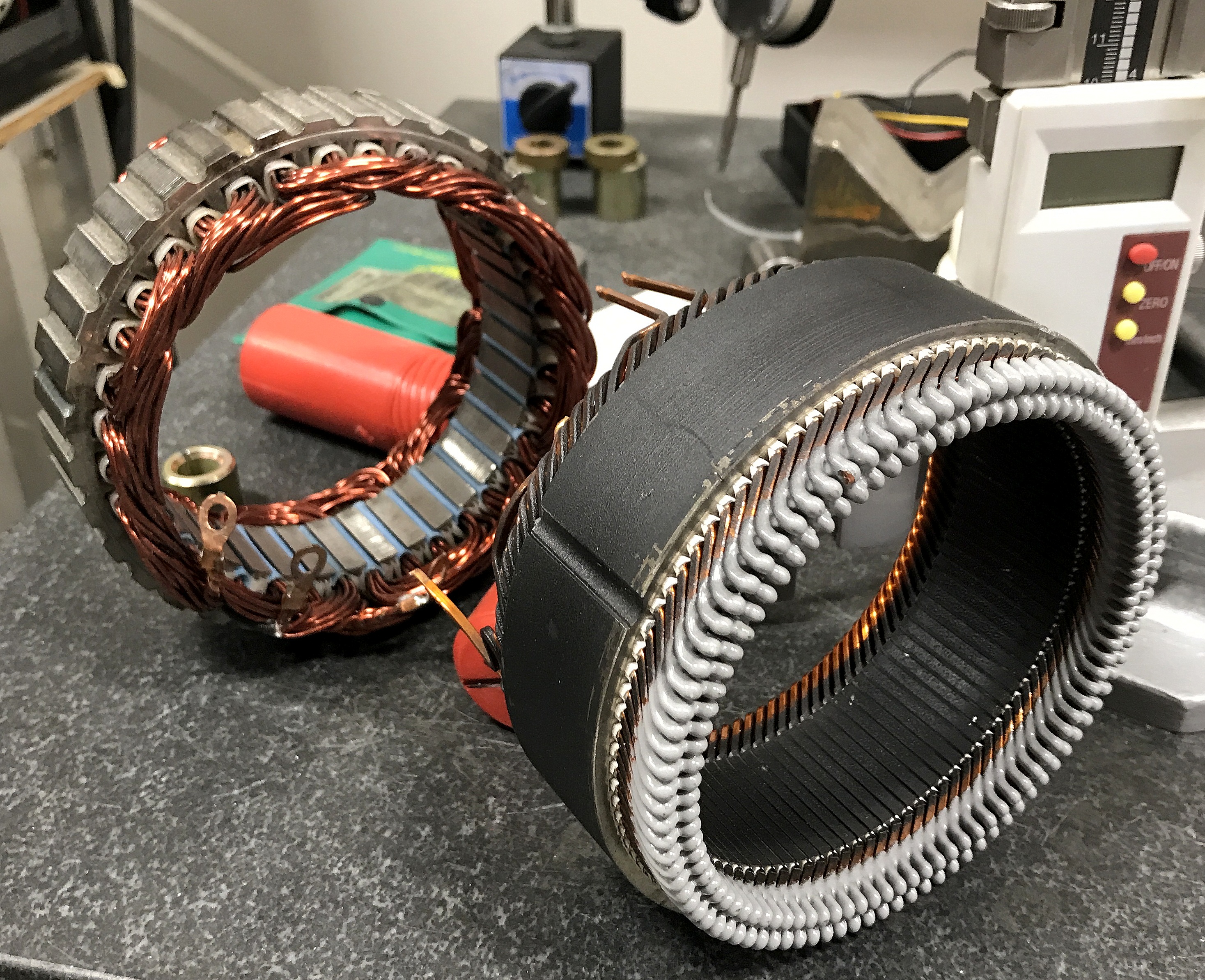
Where the hairpin design alternators shine is in better efficiency, which means higher output a low RPM. For applications where we have a slow turning engine or a need for a high percentage of full output at a low RPM such as charging at anchor or low RPM motor sailing.The hairpin design can produce a lot of current at low RPM.
The AT series really shines for low RPM charging. However, please don’t be confused into thinking you can run these alternators full-bore into a 1600Ah bank without some sort of temp protection strategy such as Belt Load Manger and an alternator temp sensor. They are still small frame alternators.
In the foreground is a Balmar hairpin stator and behind it a standard wound stator. You can see why the hairpin design can deliver so much current at low RPM when compared to a standard designed stator.
Alternator Mount Styles
For marine applications there are four basic mount styles that make up most of the installations;
1″ Foot – Westerbeke, Volvo, Perkis, Cat etc.
2″ Foot – Perkins, Universal Diesel, Vetus, Cummins, Volvo etc.
3.15″ Saddle Mount – Yanmar & some Mitsubishi/Westerbeke engines
J-180 Saddle Mount – Large diesel engines such as Cummins, Detroit, Cat etc.

1″ & 2″ Foot Mounts – For aftermarket use most manufacturers will build 1″ foot alternator that can easily be converted to a 2″ foot with the addition of a spacer or spacer kit. This makes a 1″ foot alternator one of the most versatile in the industry and it has the widest engine fitment range.
3.15″ Saddle Mount – These frames are also commonly known as dual-foot or Hitachi mount alternators. The popularity of the Yanmar marine engines is so vast that it makes sense for aftermarket performance alternator builders to produce a model that specifically fits Yanmar engines. A saddle mount alternator, such as the 3.15″ style, may also be used in many single foot applications, with careful use of spacers. Saddle mount alternators feature a *drift bushing.
J-180 Mount – The J-180 mount is fond on large frame alternators and is very similar in design to the Yanmar saddle mount. The scale and the ID width is approx 4″ between feet and it uses uses a 1/2″ pivot bolt as opposed to a 3/8″ or 10mm bolt. Saddle mount alternators feature a *drift bushing.
IMPORTANT: Not all alternators, with a similar mount style, share the same offsets and this is why careful installation and proper alignment are critical.
Belt & Pulley Choices
No discussion regarding a marine alternator installation would be complete without discussing belt & pulley choices. Until very recently the marine industry has supplied most engines with single or dual v-belts to drive the stock alternators. The use of a single v-belt was marginally suitable when boats had very little DC load or demand but today many boaters have far exceeded the capabilities of a stock 30-60A alternator and have also often exceeded the capabilities of a 3/8″, 1/2″ or even a 5/8″ single v-belt. Some owners, who’ve been overwhelmed with belt-dust, have increased the alternator pulley size to yield more belt to pulley surface area but, this is a Band-Aid solution that results in poor alternator performance due to reductions in alternator RPM.
“Industry Accepted” Recommendations for V-Belts
- 3/8″ V-Belt = 80A
- 1/2″ V-belt = 100A
This guidance can be a truism, to some extent, but it will require;
- Impeccable Alignment
- Near 180 degrees of belt wrap
- Extremely clean pulleys
- Relatively short bulk charging duration’s
- A high quality belt
Realistic Maximum Amperage Recommendation
- Single 3/8″ or 10mm V-Belt = 70A
- Single 1/2″ or 13mm V-Belt = 85A.
Limitations of V-Belts
Lower HP drive capability – When compared to flat style multi-rib belts
Prone to over tightening – Many a boat owner or marine techs have over-tightened a v-belt in an attempt to minimize slippage or belt dust but in the process damaged a water pump or other accessory drive. Over tightening a v-belt does not really aid in less slippage and can actually have an effect that is opposite the assumed outcome.
Excessive frictional heat – This heat can actually damage the alternators front bearing and transfer excess heat into the alternator. Frictional pulley heat can also be exacerbated by the use of cheap stamped steel pulleys (see image below) which tend to expand the V gap as they heat up. This can cause the belt to become loose under load. Using billet machined pulleys can help to minimize this.
Engine choking belt dust – Many v-belts contain abrasive materials such as Kevlar or Aramid fibers. When these abrasive fibers are turned into belt dust it can actually cause damage to engines. Diesels use and need lots of fresh air for the combustion process and that air needs to be free and clear of abrasive contaminates. The idea that a marine diesel does not need an air filter can be an engine damaging old-wives tale. The image below illustrates why a quality air filter on your marine diesel is a good idea.
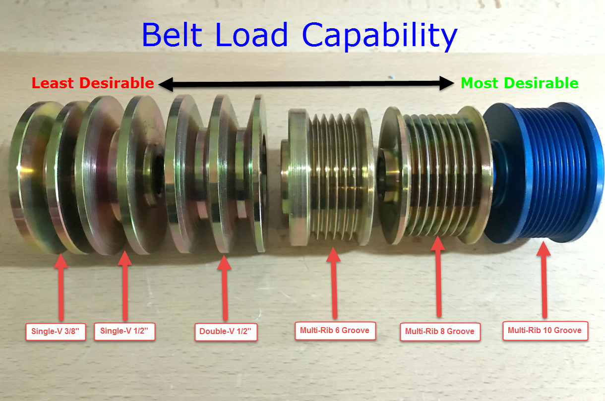
Typical Marine Pulley Types
Multi-Rib belts, often referred to as “serpentine belts” or flat belts are a more efficient design and can drive considerably more HP without developing the same level of frictional heat. Flat multi-rib belts approach drive efficiencies of 99%+ where a v-belt is nearly 2.5%-3% less efficient. Even with perfect sizing and loading the v-belt is developing more frictional heat.
For owners who desire more amperage capability from their engines, manufacturers such as Balmar/Alt-Mount or Mark Grasser DC Solutions (now out of business) are offering custom multi-rib pulley kits. These kits bolt onto your existing engine and are a sure fire way to drive more HP with less belt tension and virtually no belt dust. The Balmar / Alt-Mount kits are usually a 10 Groove or a 6 groove design, depending upon the kit,. The Mark Grasser DC Solutions kits utilized an 8 groove pulley design.
The most common pulleys for marine engines. Rated by effectiveness:
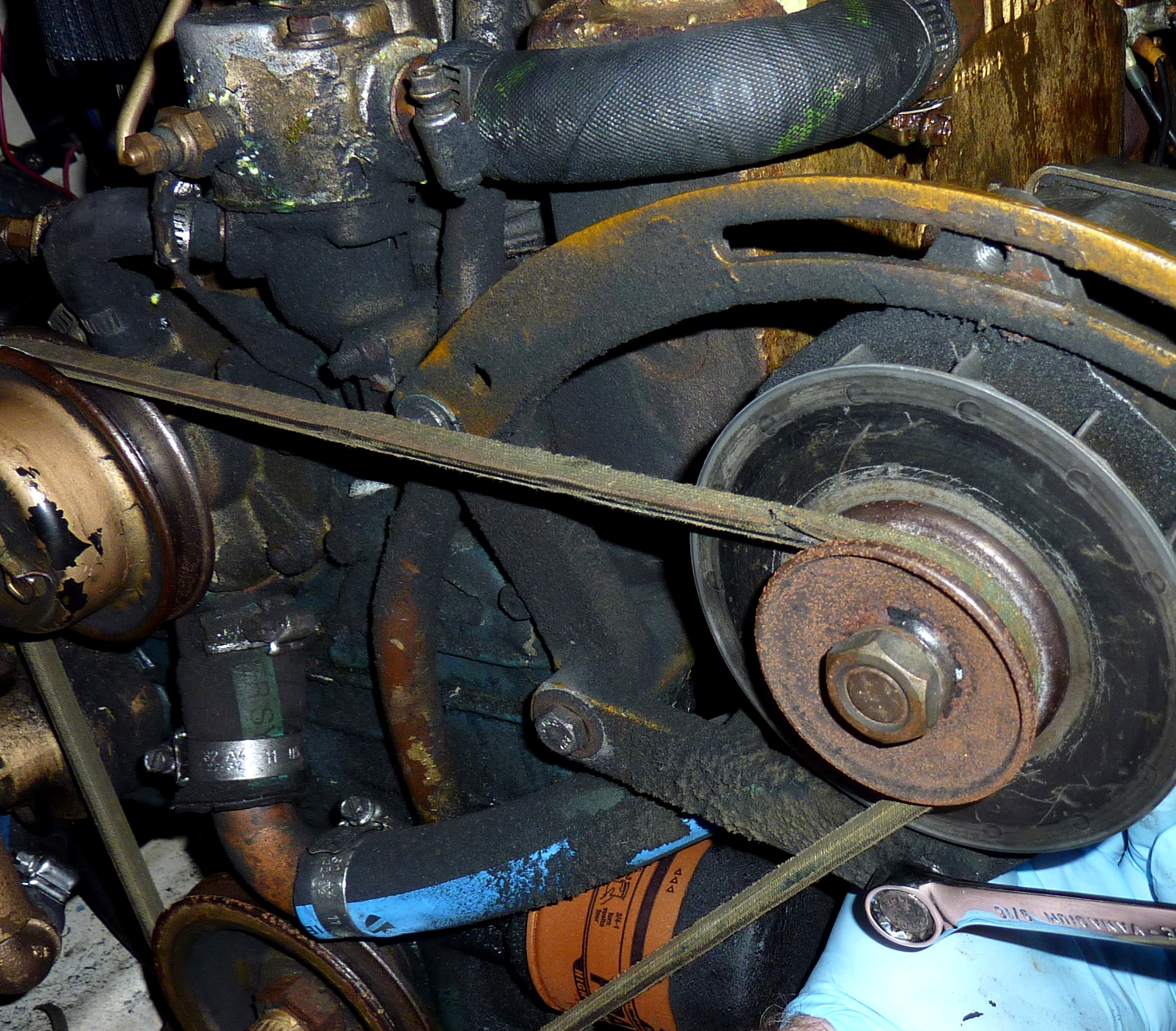
Belt Wrap Considerations
When considering an alternator upgrade the desired amperage and the actual belt-wrap of the existing pulley can’t be ignored. Many alternator belts are also used to drive water pumps, as seen here, and this means the belt wrap around the alternator pulley is going to be less than optimal. Less than optimal belt wrap usually means your single v-belt will not strictly adhere to the industry max capability recommendations of 80A for a 3/8″ belt and 100A for a 1/2″ belt. These recommendations are assuming a near 180 degree wrap around the alternator pulley. This brand new alternator installation is a prime candidate for a serpentine kit.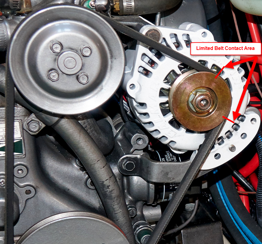
Pulley Cleanliness
When upgrading your charging capability one of the best things you can do is to ensure your existing crank pulley, as well as your water-pump pulley surfaces are clean and free of rust or corrosion. Rust and corrosion act like sand paper on your belt/s and create rapid wear, a need for continual adjustment, and excessive belt dust. To remedy rusty & corroded pulleys a drill and wire wheel, or a Dremel type tool with wire wheel, can be used to clean the pulleys to bright metal. In this image a water-pump pulley gets a cleaning. You’ll be amazed at the difference this one small step can make.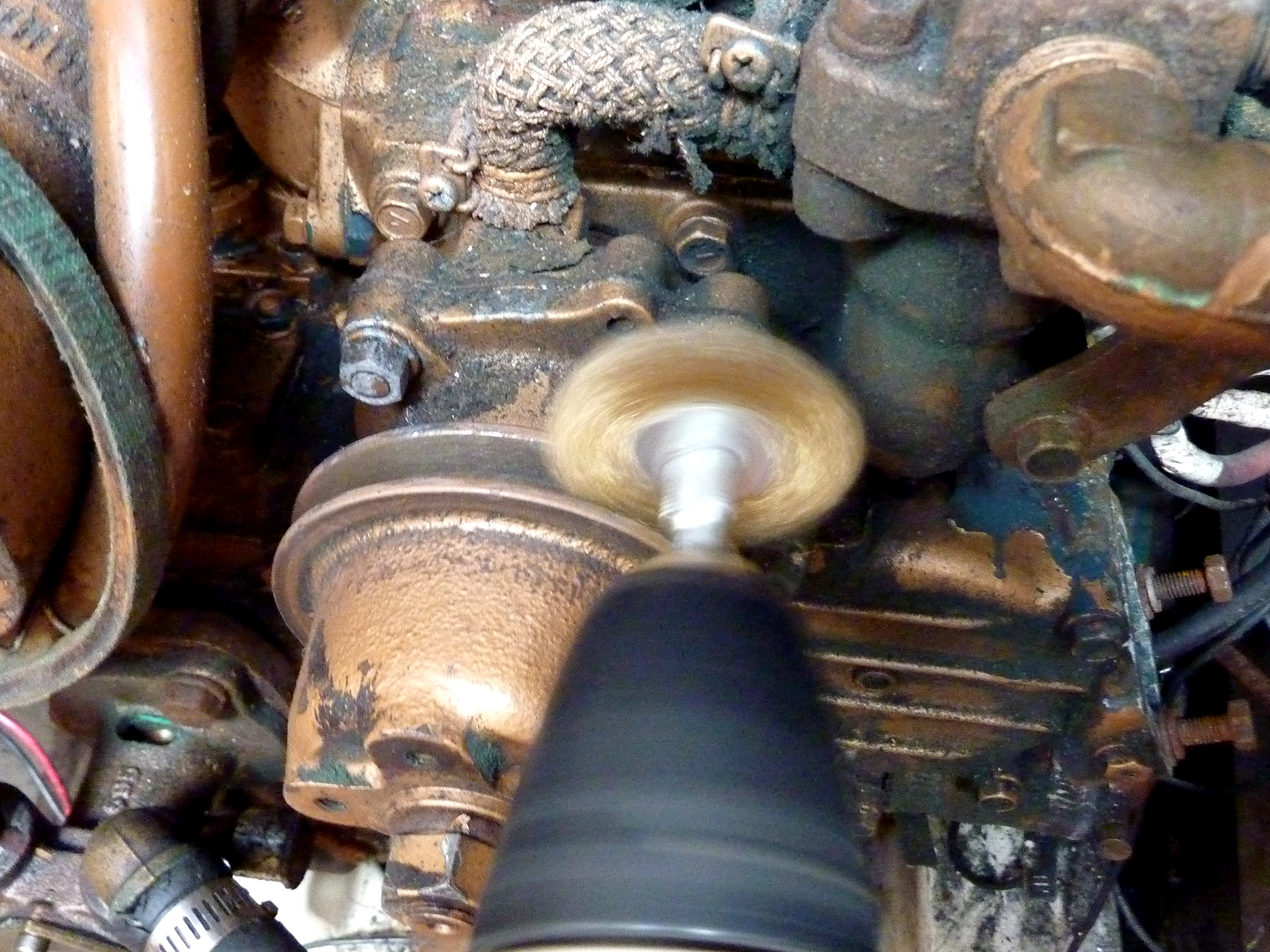
What About Double-V Pulleys?
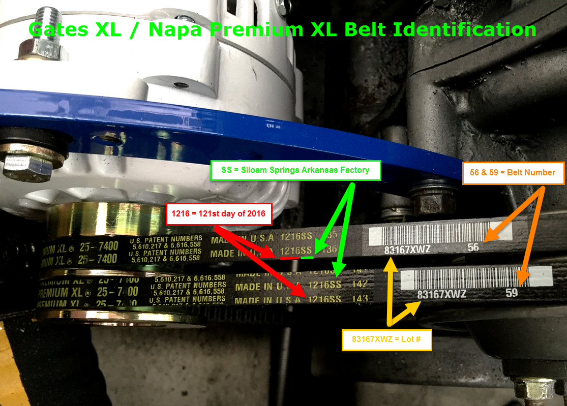
Double-V pulleys are pretty common and perform far better than a single-V pulley arrangement but they too can be more problematic than a multi-rib pulley system. If your vessel already has a double-v belt pulley system I would recommend using it, unless you desire more than 130A to 140A of alternator charging. Years ago, when industry used lots of v-belts, finding a *precision matched pair of belts was pretty easy (*Gates terminology), today, not so much. For the set up pictured below, Gates recommended their Aramid reinforced Predator Industrial Series belts but with limited sizing, in the industrial line, and the inability of the Predator series belts to wrap the alternator pulleys small outside diameter properly, the Gates XL Series was the next best choice.
Gates, Dayco and other belt manufacturers claim that today’s manufacturing process has eliminated the need for “matched pairs“. Interestingly enough Gates still offers “precision matched pairs” for industrial applications customers? If there is “no need for this due to manufacturing” then why? Precision Matched Pairs are actually hand measured and matched but sizing is really quite limited when compared to marine application needs. For a high amperage marine application finding a well matched pair can be difficult at best. Your best bet is finding your largest NAPA, or other large automotive or industrial belt distributor, such as Motion Industries, and choosing your belts by:
- Same Date Code
- Same Factory
- Same Lot Number
- Closely Matched Production Run Numbers
This is a guide to deciphering Gates numbers and matching the belts as closely as possible:
Pulley Width Considerations
Unless you’re using a Balmar 1/2″ wide pulley, be careful to only use a 3/8″ width pulley if you have a 3/8″ wide belt. Balmar specifically machines their 1/2″ pulley, such as the 61-0010, a bit deeper so that the 1/2″ pulley can be used with a 3/8″ wide belt. Most other 1/2″ wide single-v pulleys are not machined this way. As can be seen here a 3/8″ belt was used on a 1/2″ pulley and it’s only fractions of a mm away from bottoming out on the flat spot of the pulley. Once this occurs you can burn out the front alternator bearing very quickly due to the excessive heat.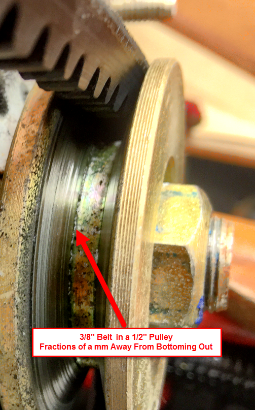
Belt Mistakes Can be Costly
In this image we have a high quality Japanese made front bearing that was literally “burned out” due to frictional pulley heat. The bearing got so hot the front seal was destroyed and the grease was literally cooked out of the bearing. It then began to squeal & howl. If you look close you can see the heat damage emanating out from the shaft side of the bearing seal, and the gap in the seal where the grease was allowed to cook out of it. This was simply a case of attempting to drive too much horsepower with a single v-belt.
Pulley Ratio Considerations
Most performance marine alternators are specifically wound for low RPM performance. This means they can develop a tremendous amount of their rated output at a low engine RPM. At low RPM, for many marine diesels, this means a slower alternator fan speed. Low fan speeds with high output is were some of the most damaging heat can occur. Always pay attention to alternator temp at fast idle, if you plan to charge on-the-hook. If the alternator gets to hot reduce Belt Load Manager and / or add some forced air cooling to the alternator, via ducting and blowers.
Also, each alternator frame has a maximum design RPM. Some older marine engines, such as those by Volvo Penta, had massively large crank pulleys that can result in as much as a 5.5:1 pulley ratio. This can actually result in over-spinning certain alternator frames beyond their max design RPM limit. Before installing any performance marine alternator, on an engine with an overly large crank pulley, please check with the manufacturer of the alternator for the maximum safe RPM. You may find you need to up-size the diameter of the alternator pulley significantly.
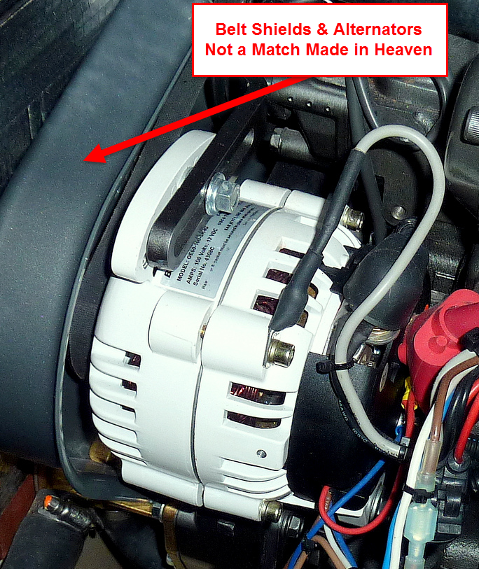
Belt Shields & High Performance Alternators – Not a Good Match
I know we live in a world where lawyers are purportedly waiting around every corner to jump out and sue you into bankruptcy but, the Yanmar lawyers have taken this threat right over the top. The belt shields on newer Yanmars really do nothing but create problems dissipating heat from alternators. If you, as a boat owner, don’t know not to stick your hands into the belt of a running engine by now, perhaps you’ll want to consider a safer pastime. I hear Trivial Pursuit is pretty tame?
Balmar has lawyers too, and they advise drilling out the belt guard for better air flow. This can help but is really just a legal Band-Aid. Internal fan alternators draw cool air in from both the front and rear of the alternator and expel it out the center. Front fan alternators draw air in through the rear and expel it out the front. Belt guards like this do nothing but make it more difficult to have a cool running alternator.
In this image the alternator is sandwiched between a hot heat exchanger and the belt guard… It’s a darn good thing they installed an alternator temp sensor.
The choice to keep, drill or to remove your belt guard is 100% your decision. Please consider the safety risk carefully when or if you choose to remove it entirely.
Alternator Position – In or Out
Here’s an insider tip that can be considered when installing a high output alternator. Ask yourself these questions;
*Where the manifold is in relation to the alternator?
*Is it right behind it?
*Do I have the room to tilt the alternator out a bit and get it away from the hot engine?
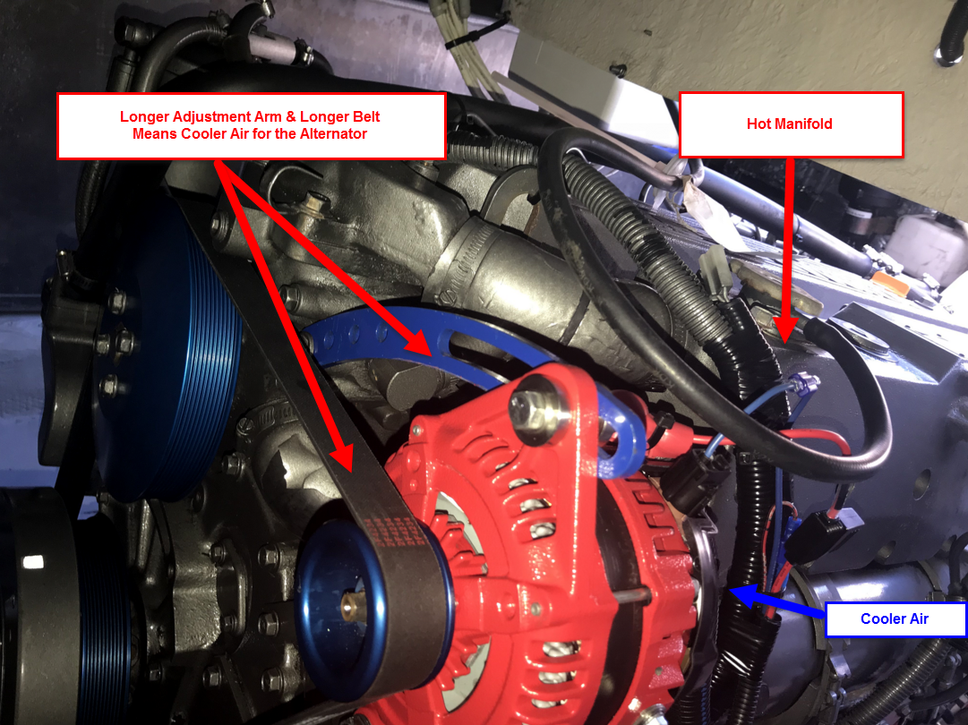
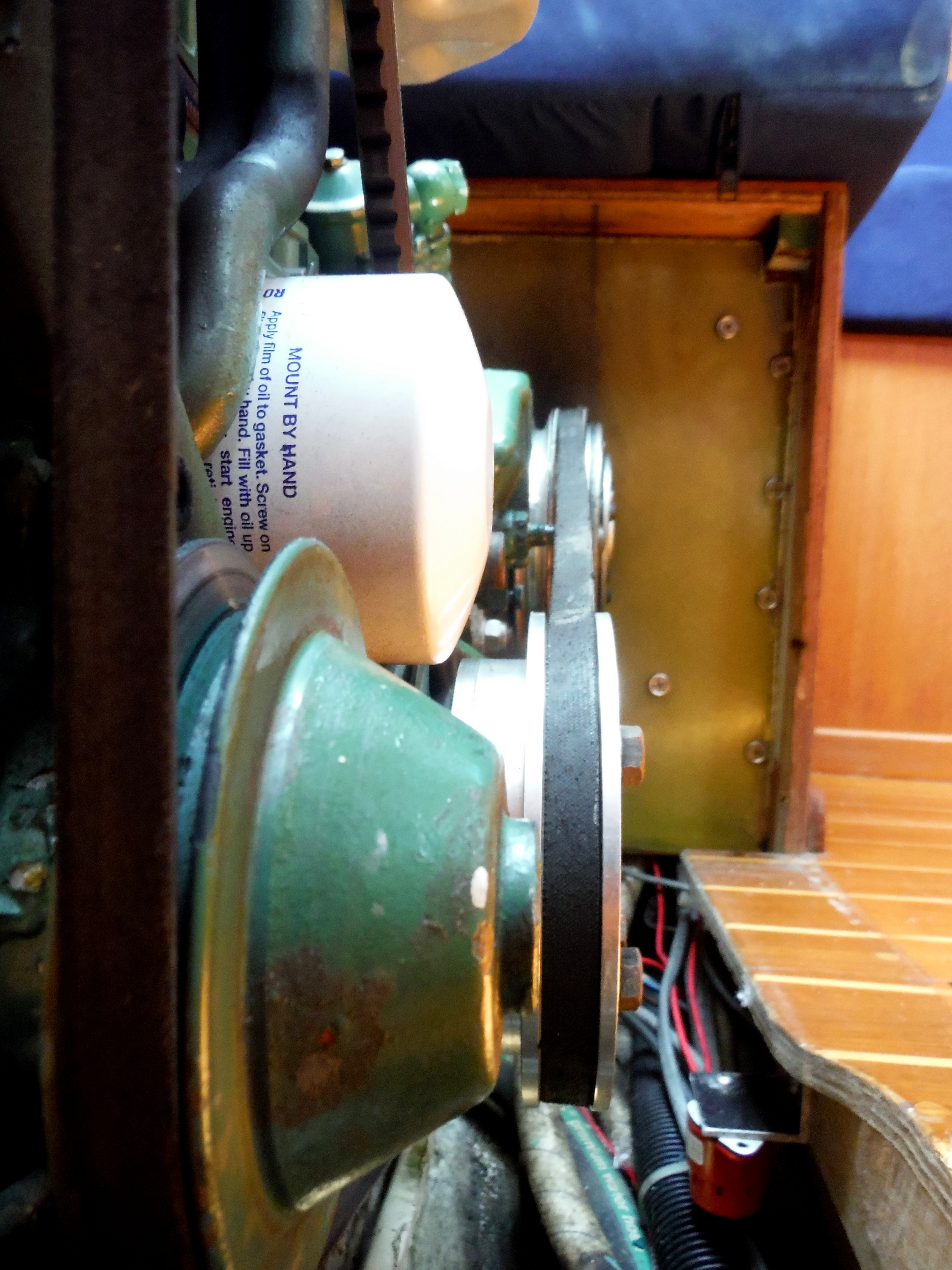
On many engines the alternator is designed to sit directly in front of a massive 180ºF to 210ºF heat source called a manifold. This particular engine room was not the best for photography but it illustrates an optional approach.
Here we are using the stock adjuster arm from Yanmar as well as the belt supplied with the serpentine pulley kit. Doing this places the alternator smack dab in front of the hot manifold making it tougher for the alternator to suck in the coolest air possible.
Stock Configuration

The choice was made to use a longer belt and adjuster arm, in this case the Balmar UAA or Universal Adjustment Arm. As can be seen the alternator is now out into cooler air and not stuck behind the hot manifold.
Optional Configuration
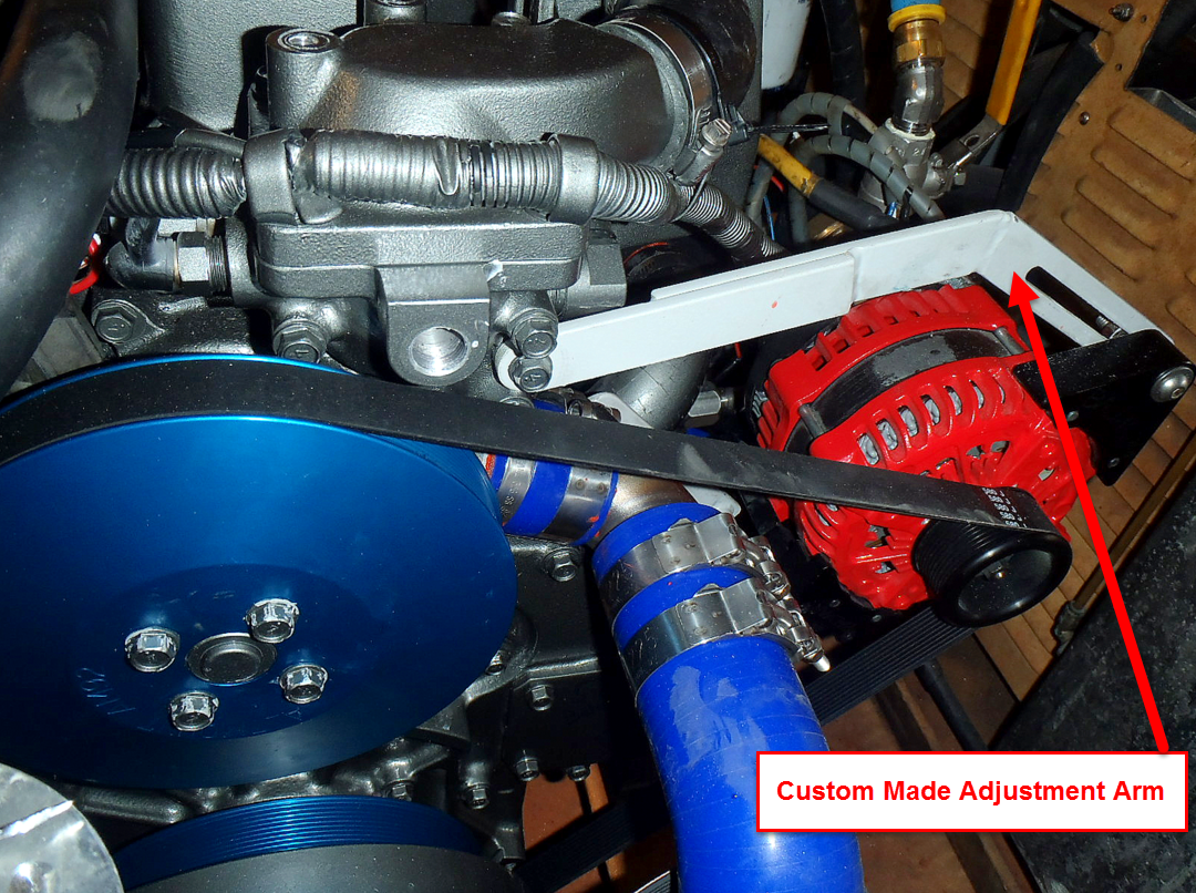
This owner really went to town and built his own adjuster arm to get the alternator out into cooler air. This is Balmar AT-200 with Alt-Mount Serpentine kit and the owner made his own adjuster arm to get the alternator out into cooler air.
Don’t be afraid to “roll your own“…
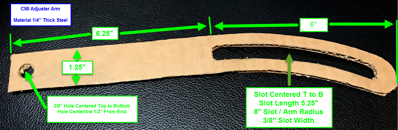
While cleaning the shop I found a template I had used for a custom large frame alternator installation. It was mocked up in cardboard, then 1/4″ plywood and then I made a drawing to give to our local machine shop. The drawings are nothing special. A custom adjuster arm, if necessary, is not very difficult. In 98% of the installations going to this level will not be necessary but it is just another option you have.
Alternator & Pulley Alignment
Perhaps the most critical step in an alternator installation is ensuring the crank pulley and alternator pulley alignment is good (water-pump too it they share a belt). In most cases, with a an upgraded alternator, they will often bolt right in and alignment will be pretty good but, it pays to check it, just to make sure.
We have two things we are looking at;
Angular Alignment Issues

Parallel Alignment Issues
Here’s an example of both an angular & parallel alignment issue:
TIP: If the alignment is so bad you can see it visually, it’s beyond bad!
Checking Alignment On-Board
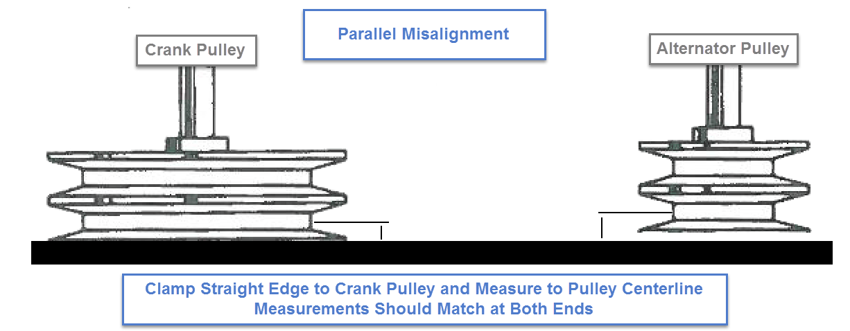
When on-board, alignment can be checked pretty easily by using a straight-edge. By clamping a known true straight-edge across the front face of the crank pulley, and extending it to the alternator and water pump pulleys we can easily check both angualr and parallel alignment. Parallel alignment is usually the more common issue but, alternator brackets made by the engines marinizer, such as on a Westerbeke or Universal, can tend to create angular issues more often than a factory made alternator mount such as a Yanmar.
For this task I generally use some aluminum “L” stock or 1/2″ square tube stock tested on our cast iron planer table for flatness. Aluminum like this is available at just about any Home center. You’ll want the straight-edge to be able to extend to both the water pump and alternator pulleys. Once clamped to the crank pulley, you can simply measure the offset from the straight-edge to the very edge of the belt or to a pulley groove center. The measurement should match at both ends.

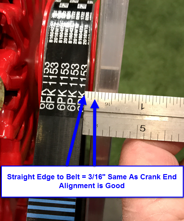
One measurement that is often confusing is when you have a crank pulley and alternator or water-pump pulley’s with varying face thicknesses. It does not need to be confusing. Once the straight edge is clamped to the crank pulley the measurement that’s important is from the straight edge to the belt edge or the center of the pulley V’s. If measuring to the center of a pulley V, on multi-rib pulleys, be sure to use the same v-groove at both ends. A divider can be used to compare end to end measurements by measuring one end then locking it and moving it to the other end. For these illustrations I have used a ruler and edge of belt measurements. Please do not use “to edge of belt” if the belt is not brand new.
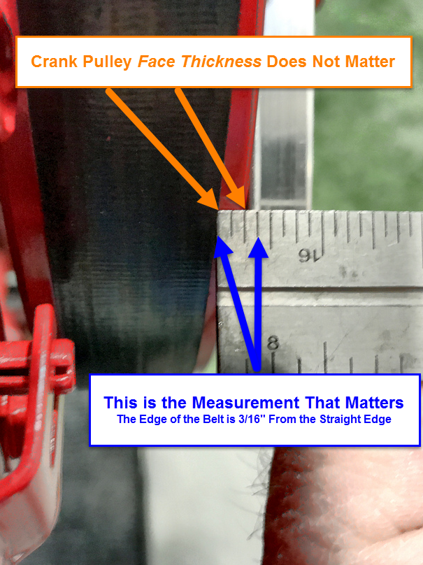
This end is a prime example of why the pulley thickness is not taken into account. As can be seen the face thickness of the alternator pulley is less than the crank end. This is why the measurement that matters is from the edge of the straight edge to the edge of the belt or the center of a V in the pulley itself. In the event that the face of the crank pulley is thinner than the alternator pulley a piece of shim stock can be used at the crank end to space the straight edge out beyond the alternator pulley.
For angular alignment the straight edge should be the same distance from the straight edge at both side of the pulley. In the photo above we can see the gap between the pulley and straight edge is perfectly parallel and angular alignment is also not an issue here.
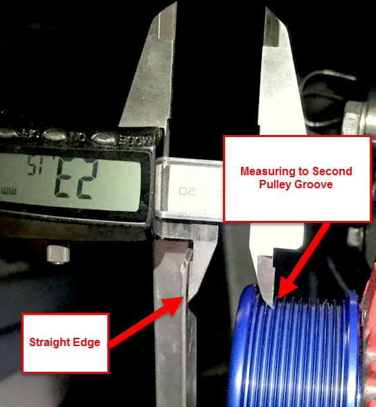
The image below represents a case where the crank pulley’s face is much thicker than the alternator pulley’s face. A measurement was made at the crank end first, from the straight edge to the pulleys second groove and then repeated at the alternator pulley end and the two offsets were compared. The distance was essentially 23.15mm at both ends or darn near perfect alignment..
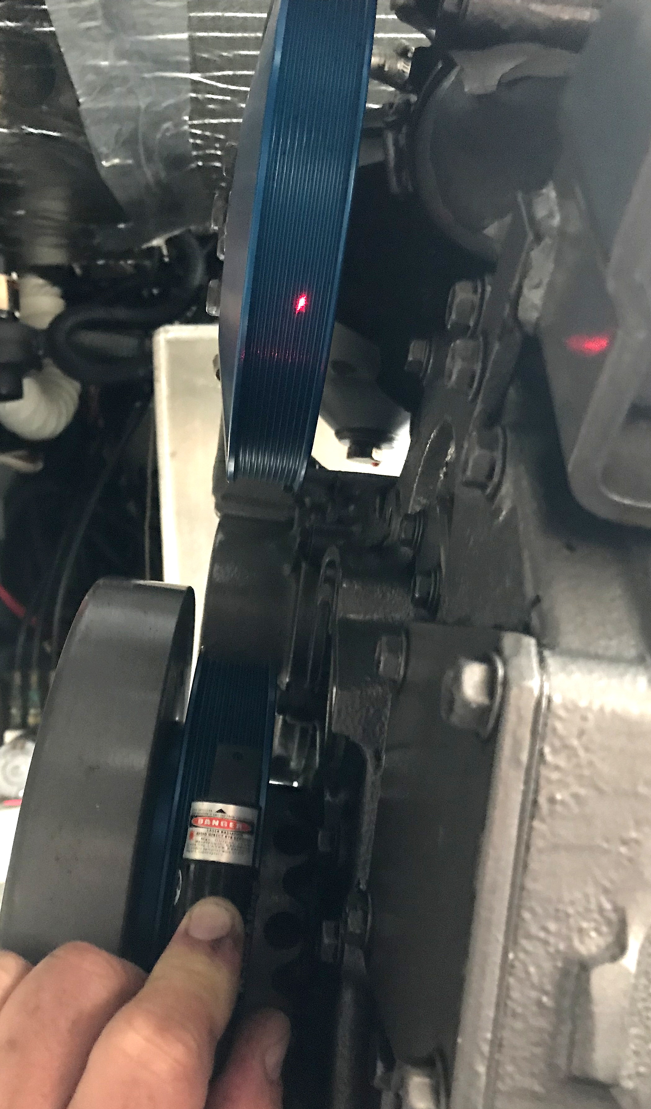
“What about laser alignment tools?”
We own a couple of these laser tools and all I will say is save your money, unless space is really, really tight. The tricks you’ve just seen remove the need for these expensive tools and the laser alignment tools do no better of a job. A $3.00 piece of aluminum stock and a ruler or your navigation dividers from your chart table are a lot less than the cost of a Gates Drive-Align Laser or similar.
Shimming & Spacers for Alignment
Occasionally you can run into a situation where the aftermarket alternator is off by a bit. For Yanmar fit alternators the most common need for alignment is to shim forward. This is good because with a dual-foot alternator, if you needed to move aft, you’re either moving the alternator mount or machining off some of the foot.
In this image two washers have been used behind the Yanmar fit alternators front foot to get the correct pulley alignment. The washer closest to the alternator foot was sanded on a piece of glass, using wet sand paper, until the correct thickness was attained. This can take a while but the right thickness washer was just not readily available. If you know the thickness you need a machine shop can also make you any spacer you need. Any washers used for shimming should ideally be the same ID as the alternator pivot bolts OD. In other-words if you have a 3/8″ OD pivot bolt use a 3/8″ ID washer and if you have a 10mm pivot bolt use a 10mm metric washer.
Yanmar 3.15″ Dual Foot – Shim Forward

Dual Foot / Saddle Mount Alternators Can be Quite Flexible
In this image we have a Westerbeke engine that used a teeny-tiny 1″ foot Mitsubishi alternator that really conformed to no “small-frame” standards other than its own. Westerbeke offers a bracket to convert to a Balmar or other 1″ or 2″ foot Delco/Motorola/Bosch frame type alternator but the pricing for this bracket is literally insane.
When a 1″ or 2″ foot alternator can’t work the 3.15″ Yanmar style dual-foot alternators can often be used in place of a 1″ or 2″ foot mount as seen below. This image shows a Balmar 6-Series dual-foot alternator mounted to the factory Westerbeke engine mount (red part). Alignment has been set and mocked up using shims and washers. Once the shim & spacer dimensions are known you can then hit a machine shop and have them make you the correct spacers in a one-piece design. In this case the multiple pieces behind the red engine mount and in front of the alternators rear foot, would be combined into one nicely machined spacer. You can always leave it as pictured too. I just prefer less shim-parts as opposed to more. I have noted what I refer to as the drift bushing in the rear foot more on this soon.
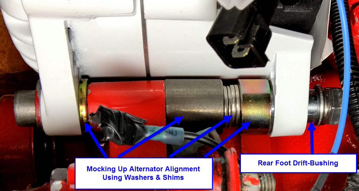
Here’s an example of what it looks like to have the spacer and shim pieces machined to minimize excess part count..

Dual-Foot Alternator Rear Foot Bushing
The Yanmar style 3.15″ dual-foot alternators (also called “saddle mount” or “Hitachi mount”) as well as the 4″ dual-foot J180 large frame alternators both use what I refer to as a rear foot “drift bushing“. It is really just a split bushing that is machine pressed into the rear foot but other than “drift bushing” it really has no identifiable name. It does however deserves some brief discussion.
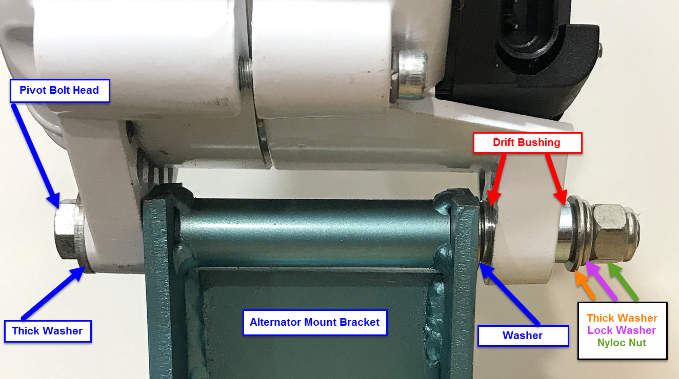
This bushings sole purpose is to compress the front foot of the alternator between the pivot bolts head and the alternator mount. It also serves to “support” the aft end of the alternator. Under no circumstances should the drift bushing ever be removed and the two feet of the alternator “clamped” by the pivot bolt..
This owner of a brand new alternator did not know what this bushing was for, so he removed it.. Oh jeez…….

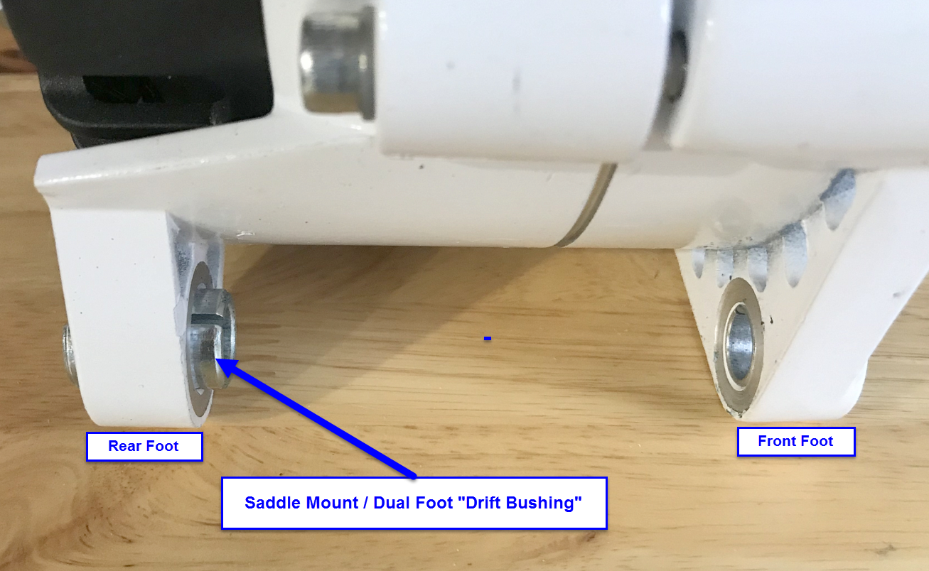
This is a saddle mount / dual foot drift bushing:
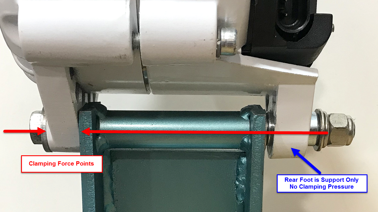
This image illustrates where the clamping pressure is applied with a “dual-foot” alternator. Only the front foot is under clamping force pressure. The rear foot is merely providing support. You can see pretty easily with this Yanmar alternator bracket why removing the drift bushing can result in breaking of the alternators mounting feet.
When installing a dual-foot alternator following the guidance below will result in a worry free installation:
Alternator Pivot-Bolts
An alternators pivot bolt would appear a rather mundane item to discuss but, using the wrong bolt can get quite expensive. In the image below the engine blocks aluminum alternator mount has been damaged by the use of the wrong size pivot-bolt. Using the wrong size bolt, one that is undersized, can allow the alternator to twist, under belt-load and can potentially cause damage.
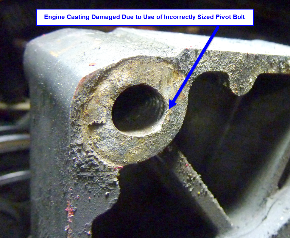
If you let the above continue and ignore checking your belt tension and alternator when you check the oil. This damage destroyed the entire front timing gear cover of the engine.
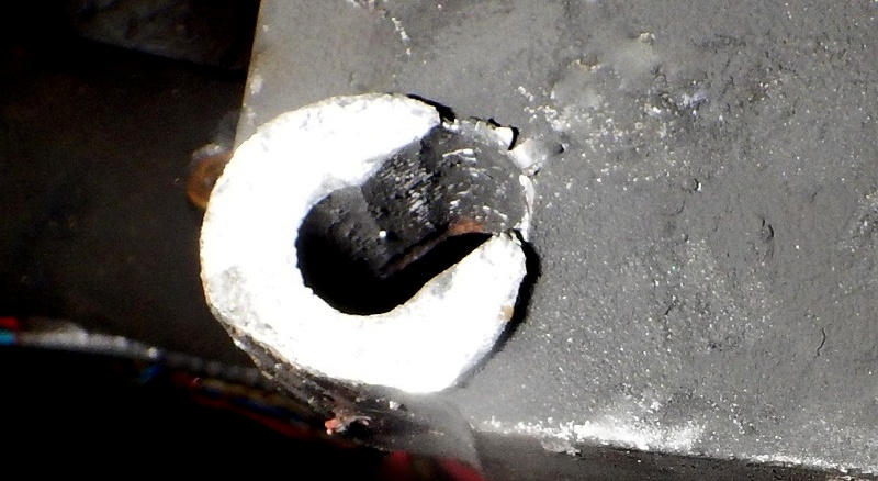
Alternators are also susceptible to pivot bolt damage:
Adjuster Arm Issues & Solutions
Issue #1
An alternator adjuster arm is normally just a piece of plate steel that connects to the engine on one end and the alternator on the other end. Its sole purpose is to keep tension on the alternator belt. The steel arm is normally slotted, as can be seen below, and the bolt clamps the alternators adjustment ear to the adjusting arm. One problem with this is that the alternator ear is soft aluminum and the aluminum gets pretty hot. Through repeated expansion & contraction cycles, and on high vibration diesels, the bolt can often become loose as happened in the left side image below. In this case the bolt actually fell out completely.
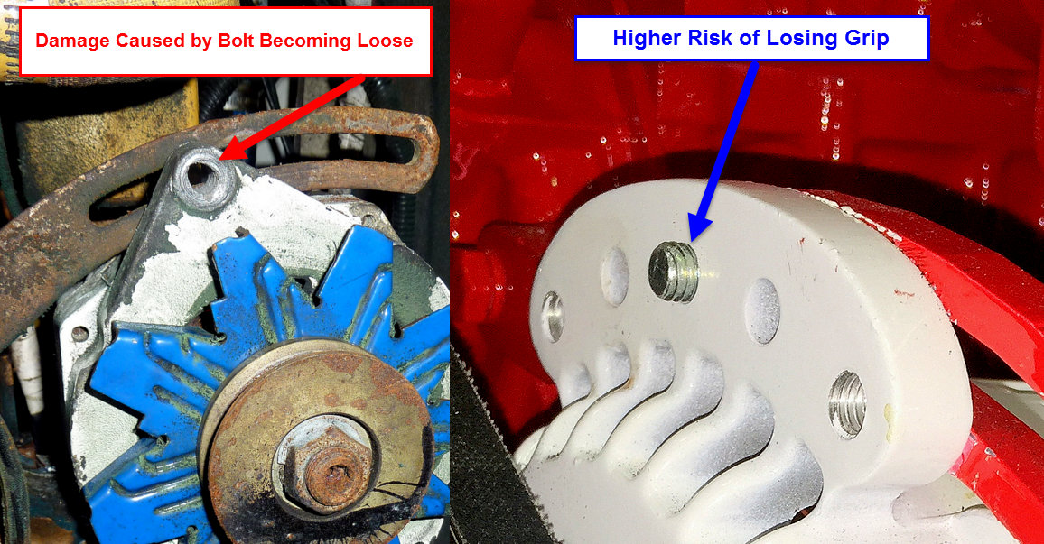
Issue #2
The second issue I see, with fairly high regularity in regards to adjustment arms, is a relatively thin washer trying to apply pressure to the slotted arm. Due to the slot there’s limited surface area to actually grab onto. What often winds up happening is the washer begins to “dish” or “cup”. Once it does this the original torque/tension is lost and the alternator ear looses its grip on the arm can slip and allow the belt to become loose. The grip on the adjusting arm below was lost when this washer “dished” under load.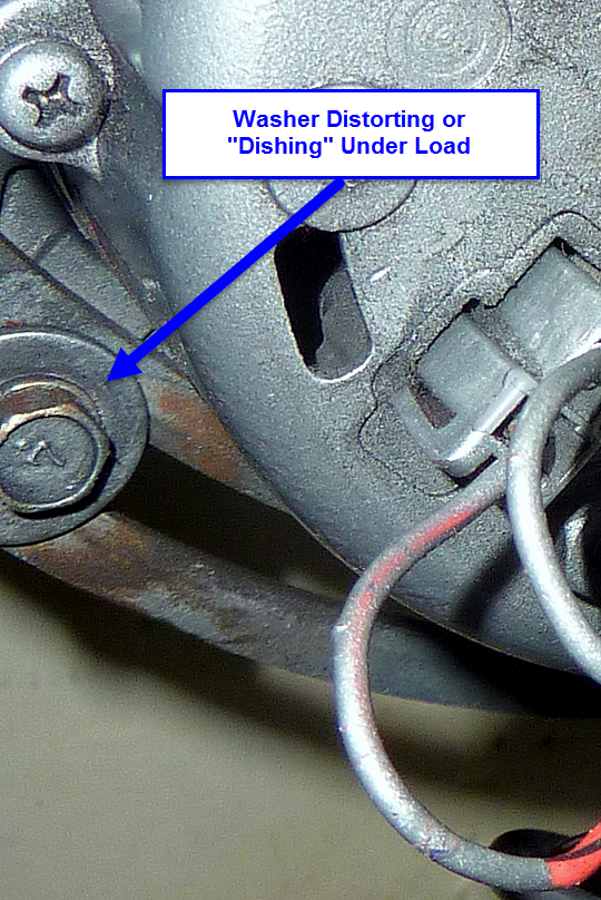
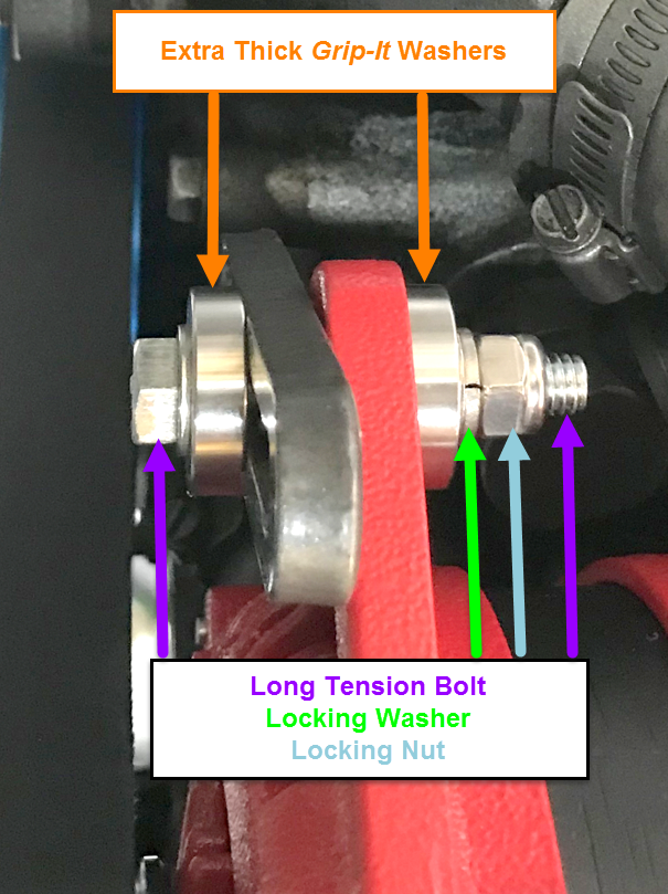
Solution’s for Issues #1 & #2
In order to alleviate the issues associated with the images above I recommend using a bolt that will extend all the way through the alternator adjustment ear far enough to accept a washer, lock washer and a nut. A Nyloc or other locking nut is an added benefit here as nylon has a much higher melting point than your alternator should ever see. On top of the longer bolt the use of *an extra thick washer, such as the CMI Grip-It Washer will eliminate washer dishing & arm slippage. (Grip-It washers are no longer available)
*The Balmar AT-165 uses an extra thick washer on both sides because the adjuster ear has a vertical slot in it. For threaded ears an extra thick washer on the adjusting arm side is all that is usually necessary.
Setting Belt Tension
Just like belt alignment, belt tension is critical for optimal alternator performance. Too much tension is not going to necessarily be better than too having little tension. Both extremes are bad. Guessing at belt tension, using the Binford Mark I Thumb Press Tool, unless your really experienced with this, is not likely to result in a good outcome. New belts also need to be “run in” and then re-adjusted. In other words don’t just install a new belt adjust it and walk away. You’ll want to run the belt under load for a period of time then make a second adjustment.
The first step in setting belt tension is to identify the longest pulley span as show below.
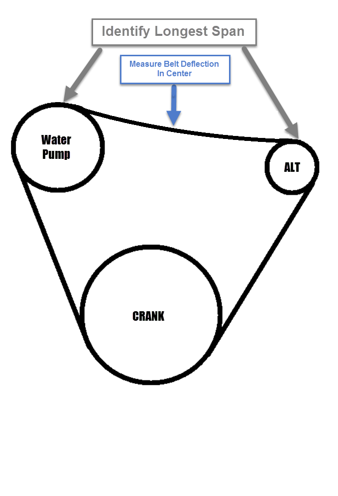
Once you’ve identified the longest belt span you can click on over to the Gates web site and used their V-Belt Tension Calculator. Simply input the type of belt you have, the belt width and whether the belt is new or used and it will give you a belt tension number to start from.
Now that you know what belt tension you need, use of the Gates KRIKIT tools can be used to measure the actual belt tension. A pencil styl tool can also be used but they are more difficult. The Gates KRIKIT tools are inexpensive and pretty easy to use.
Just place the tool in the middle of the longest span, align it in parallel with the belt and press until you hear/feel it “CLICK”. Now carefully remove the tool and read where the plastic arm is flush with the aluminum gauge. There are two Gates KRIKIT tools one goes to 160 pounds and the other to 320 pounds. The most useful for our applications is the KRIKIT II PN 91132 (bottom tool in image below).

Balmar Serpentine Belt Tension:
For Balmar AltMount J10 belts, these are adjusted similarly, by deflection, but not to the same spec as a v-belt. With a 10-groove J-section belt, the correct tension is 1/32” of deflection, for each inch of belt span between pulleys. Deflection pressure is 25 pounds applied in the middle of the longest span. A “pencil type” deflection tester, such as the Gates 7401-0076 is used to test for the 25 points of deflection.
Setting Belt Tension:
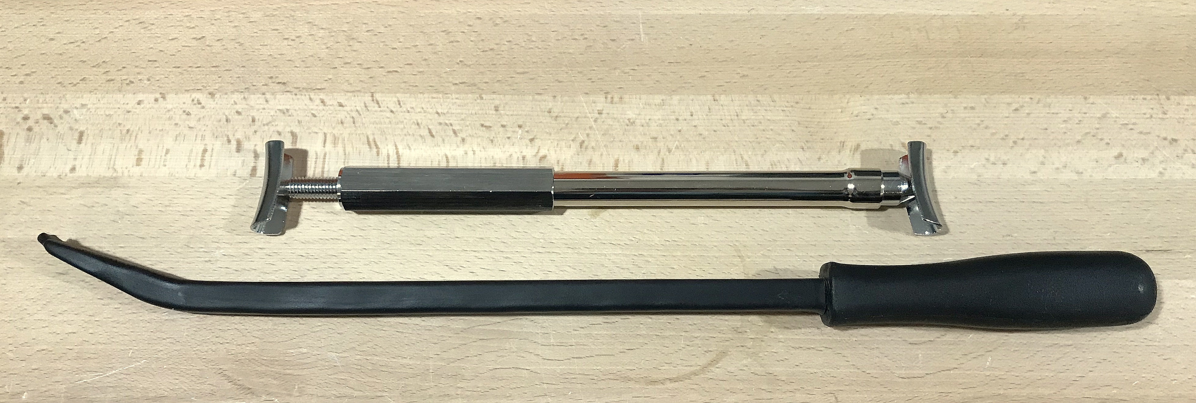
For placing tension on the belt I am pretty old school. I still use, nearly 90% of the time, a pry-bar with some heavy duty heat shrink over it. It works really well and the heat shrink prevents scratches on engines and alternators. You just need to find a good point to land it on the engine and alternator.
At the shop here, we also own a product called a Supco Belt Jack. This one, shown on top in the photo below, is the shops fourth and last one. I find this tool entirely under-designed and woefully inadequate. Hopefully this can save you some headache and money. This one is brand new because the last three broke where the pulley pad meets the jack. The welds seem to fail no matter how careful you try to be with it. Even when they do work, and it will for a short period of time, I still prefer the old school pry-bar method. If you feel you want a belt-jack, to adjust your belt, one can easily be made from an old turnbuckle for a lot less money. Done correctly it will likely also be considerably more robust than the Supco Belt Jack.
The best & easiest way we’ve found to adjust alternator belt tension is with the Balmar UBB – Universal Adjuster Arm With Belt Buddy. This is an excellent addition to any alternator upgrade you’re considering tackling.
Good luck with your project and happy boating!!
Like What You Saw Or Read?
Would you like to see more articles like this? Is so feel free to donate, support the site and keep it growing.
Please DO NOT feel obligated at all. If you like it and want to make a small donation than that’s all I ask.
Your donations help keep the content coming and also help keep it free.
Click the DONATE button below if you would like to make a donation via PayPal.