Pump Removed
This article is going to assume you have the skills to safely and easily remove your own water pump from the engine. This one is easy and uses four bolts and a gasket to mount to the timing gear case on the engine.
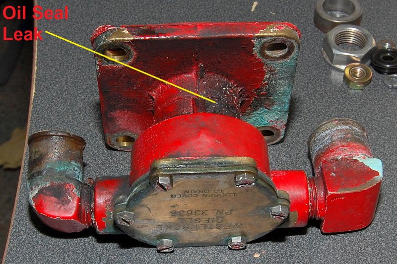
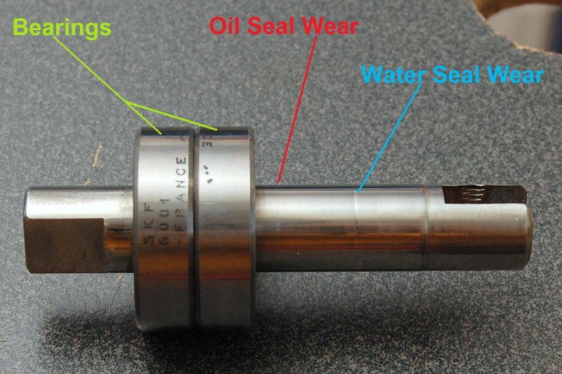
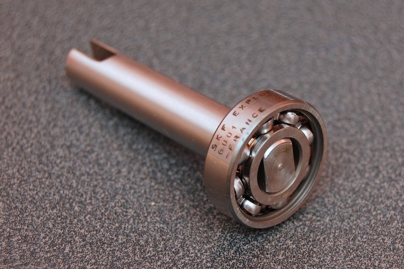
In this photo you can see how the pump came off the motor. While not leaking badly the oil seal side was weeping a tiny bit of oil as shown. Also, when they installed this motor they used 1″ hose on a 7/8″ hose barb so there was some water leakage that caused some of the corrosion. This pump appears to have never been rebuilt and the motor has 2878 hours on her, so raw water pumps can last a long time.
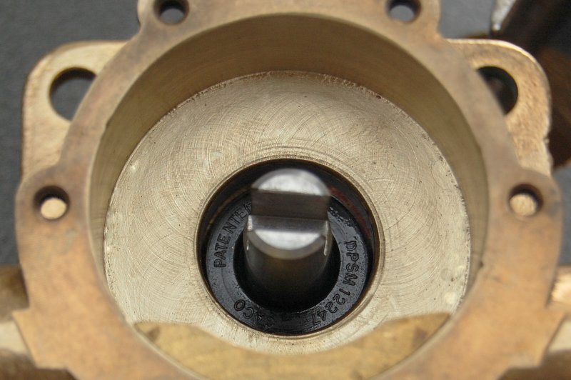
This raw water pump is made by Johnson Pump as a specific OEM unit for Westerbeke. Unfortunately Johnson Pump will not sell you parts, other than an impeller, due to OEM agreements with Westerbeke.
A new Westerbeke pump is $480.00 and the rebuild kit is $130.00. This kit includes literally everything but the pump body. Rebuilding is the cost effective and obvious choice, provided your pump body is in good condition.
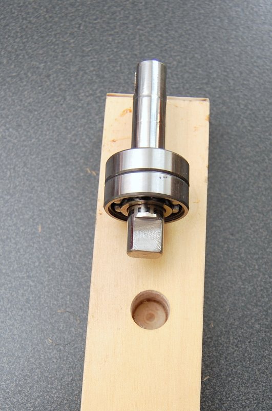
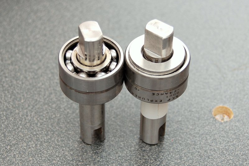
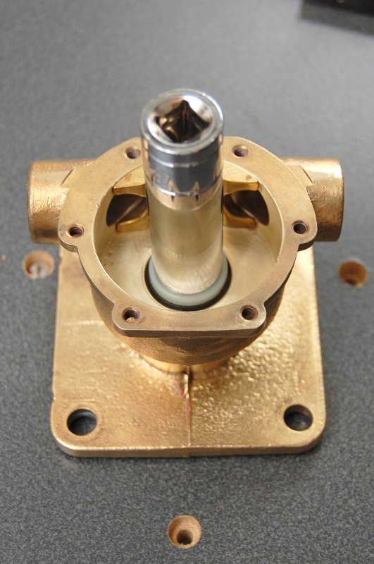
Pump Internals
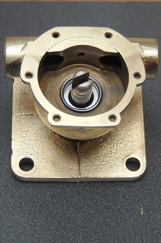
This image shows the pump shaft, the cam and the water seal.
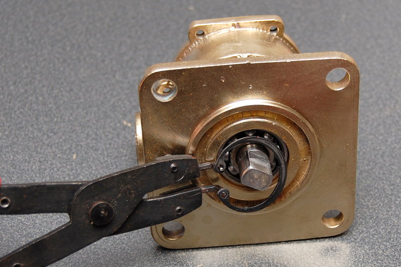
Remove The C-Clip
Raw water pumps, while similar, all have a few features in common; a pump body, shaft, impeller, seals and either bushings or bearings.
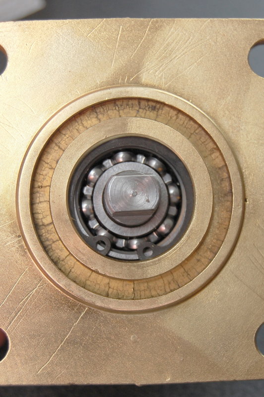
This particular pump uses two bearings that are pressed into the pump body then retained with a c-clip.
To remove this clip you will need a set of c-clip pliers. You will need the type that pinch rather than spread when you squeeze the handles. Sears, and other tool retailers, sell these and they are called everything from “retaining ring pliers” to “circlip pliers” to “c-clip pliers”.
Removing the c-clip is as easy as it looks. Simply insert the pliers tips into the retaining ring holes, squeeze and then lift out the ring.
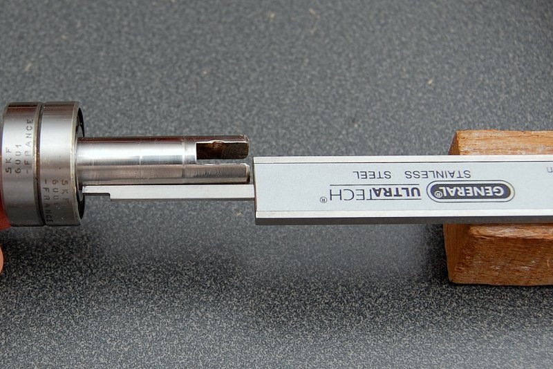
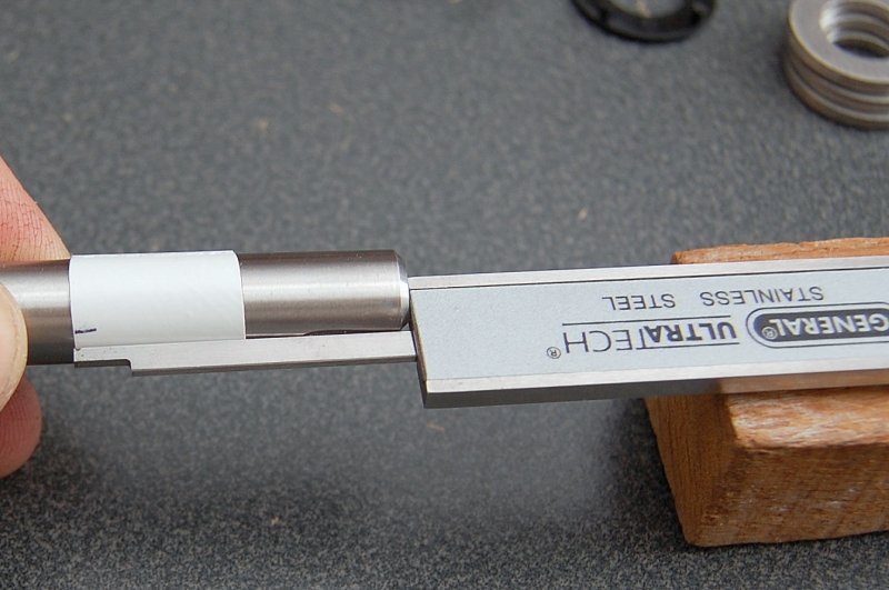
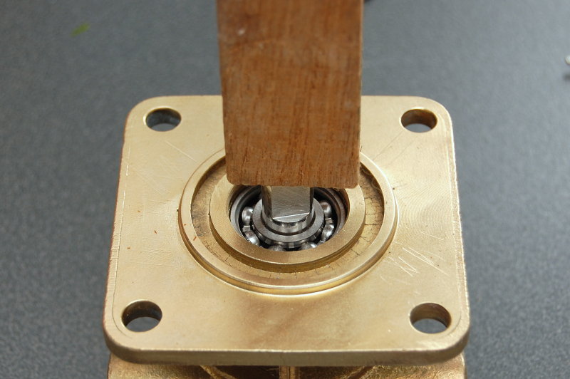
Drive The Shaft Out
Once the c-clip is removed you’ll then need to drive out the shaft. On pumps with bushings the shaft generally just slides out but on pumps with internals roller bearings you’ll need to press them out. I used a hole in my work bench, that is for clamping, router etc., to lay the pump on. The hole accepted the shaft & bearings when I tapped it out. Be sure to have something below the hole to catch the shaft or it could land on cement and become damaged or scored.

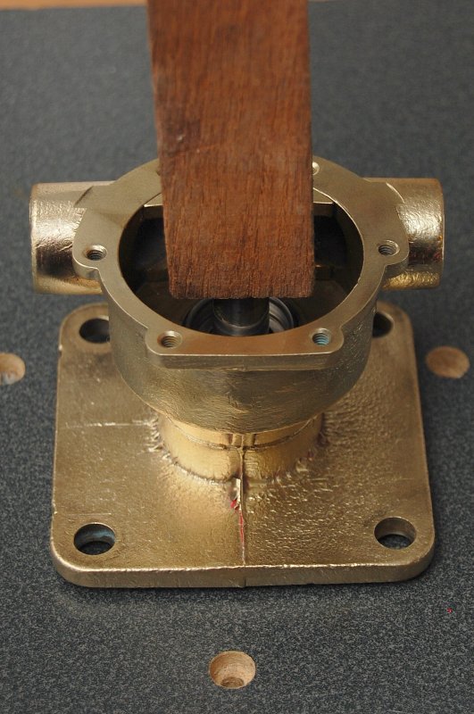
I Used A Block Of Wood
When driving the shaft out it would be advisable to use a press but most boaters don’t have one so I am showing you an alternative method. If you are of a mechanical mind set and own a lead or brass hammer then it would be OK to tap directly on the shaft as brass and lead are softer than the shaft material. If you do not own a soft metal hammer simply insert a block of wood such as Maple, Oak or Teak, as I have done here, and tap on the wood with a regular hammer.
Please remember this is a light tapping not a smashing or pounding.
If the shaft won’t come out, with some gentle taps, add some PB Blaster, let is soak over night, and try again. If you still don’t have any luck drop it at a machine shop and for about $5.00 or $10.00 they will press it out for you. I have never seen one that required this, but with boats anything is possible..
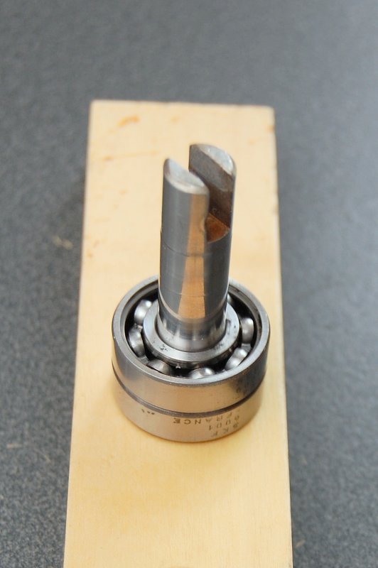
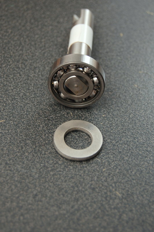
The Shaft Is Out !
Here’s a break down of the shaft & bearings. This shaft uses two bearings which are bathed & lubricated from the motor oil in engine. If you look closely you see the grooves or marks where both the oil seal and water seal spin on the shaft.
This particular pump shaft should not be reused due to the scoring. While it very well could be re-used, with new seals, there is not much sense going to all this trouble and effort and then not doing it right. The scoring could prevent issues with the new seals so it’s best to just replace the shaft.

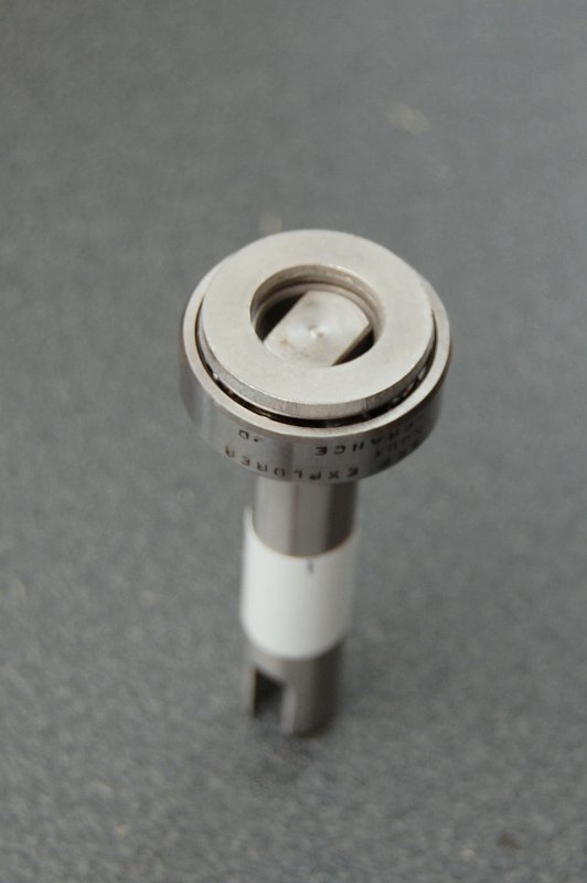
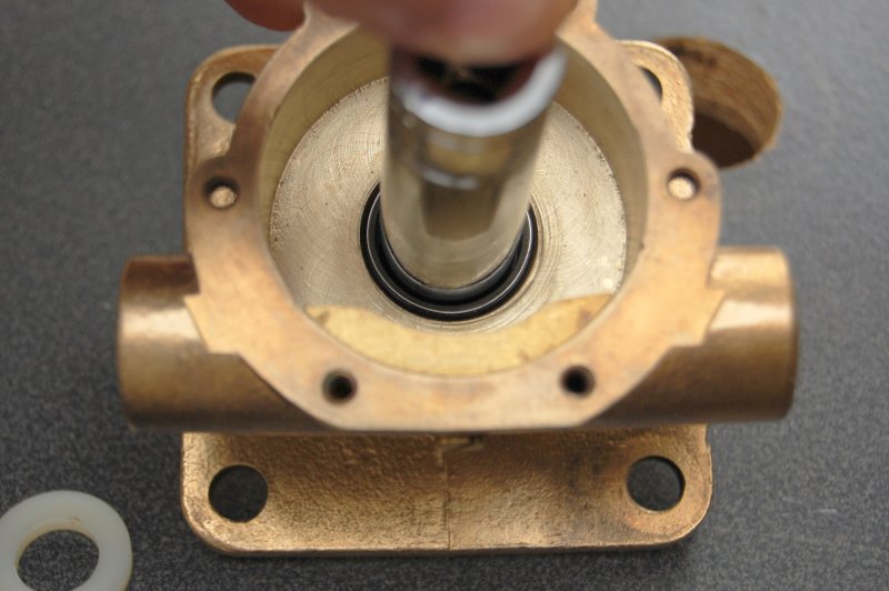
Seal Locations
This is a well designed pump. The oil seal is isolated by a weep slot or weep hole from the water side of the pump and seal. Even if the water side seal were to leak, the water will just drain out the weep hole. If the oil side were to leak it too would simply drain out the weep hole. Neither side of this pump can pressurize or leak into one another.
On occasion I have seen weep holes plugged with dried salt. In theory this could create some pressure that may press though a weak oil seal when the engine was of and the seacock open. With the engine running the crankcase becomes pressurized and should reject the water.
I have yet to see any water in the engine oil, even with a salt encrusted weep hole. It is quite possible that if water did get in, it was so minimal it was evaporated off with engine heat. Either way, if you have dried salt, water leaking, or oil leaking you’ll need to rebuild the pump.
Unfortunately some pumps, by certain makers, do not have or utilize adequate weep holes so a water side leak could inevitably leak into the engines oil or vice versa.
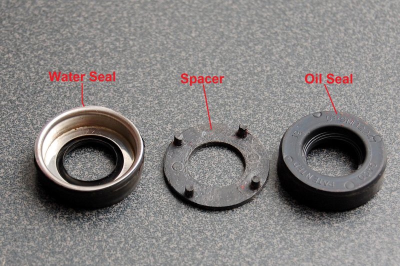
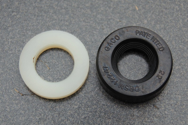
The Seals
Here are the actual seals. These two seals, when pressed into the pump body, are constantly separated by the spacer so they do not settle or compress against one another and risk oil/water or water/oil contamination. The spacer sits, and is captive, right over the weep hole to let a leak drain and become visible and detectable.
It is very important that the four little feet on the spacer face the oil seal when reinstalling the seals! The flat side of the spacer faces the water pump seal and the feet face the oil seal.

The Rebuild Kit
As of this writing the replacement for this pump was $480.00. I only paid about $130.00 for the rebuild kit, which makes it a very good value. This particular kit contains every single gasket, screw, washer and piece that makes up this pump other than the pump body casting itself. Buying a rebuild kit and doing this job yourself can represent a tremendous savings over buying a new pump.
This kit included the following:
- Water seal
- Seal spacer
- Oil seal
- Shaft
- Impeller
- Impeller lube (Glycerin)
- Cover plate
- Cover plate gasket
- Cover plate screws
- Cam
- Cam screw
- Cam washer
- C-clip
- Bearings
- Shaft
- Pump to engine gasket.
Sadly, not all pumps have re-build kits available. If not there is a great company in Florida called Depco Pump. Depco can usually get you what you need or perhaps even sell you a re-built pump.
EDIT: Since writing this article Westerbeke has increased the price of this rebuild kit to $195.95
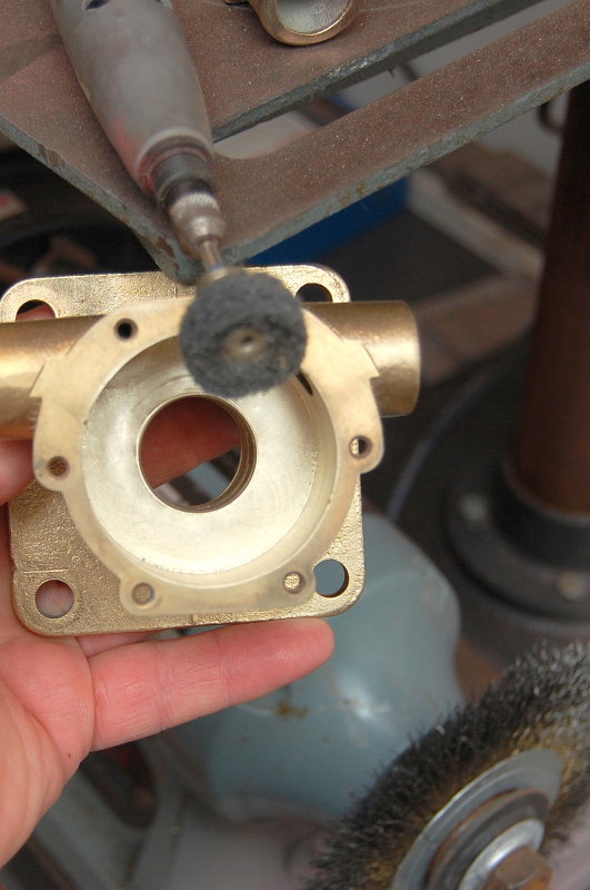
How Did It Get So Clean ?
I know some will wonder how this pump went from that grungy old thing to looking so shiny & new? It’s easy, I use a stainless wire wheel on my bench grinder and burgundy colored Scotch-Brite discs on my Dremel. I clean the cover plate and pump gasket surfaces with wet sand paper and honing oil on a piece of 3/8″ thick glass for a smooth surface.
Putting It Back Together
The first thing I re-installed was the pump cam. Be sure to use the small copper crush washer that came with the rebuild kit or it will leak out of the screw hole..
Install The Bearings On The Shaft
This task is perhaps the most difficult of the entire process. The bearings need to be pressed onto the shaft and it’s a very tight fit.
I used an old trick that was taught to me years ago for doing just this sort of thing. I simply heated the bearings, in the toaster oven to 200F (quiet, my wife doesn’t know I cook bearings..). At the same time I had the shaft in the freezer.


Shaft In The Ice Box
Here’s the shaft chilling down in order to shrink it ever so slightly.
Did Not Work Out
While I was able to get the bearing started it just did not work out as I had wished it would. The temperature of the larger mass of the shaft quickly cooled the bearing race and it ceased sliding onto the shaft. Damn, sometimes these old tricks don’t always work as well as they should.
The Home Made Bearing Press
I wanted to be able to show how to do this without needing to use a shop press. As long as you have a bench vise you can do this job.
My first task was to drill a hole just slightly bigger than the shaft in a 3/4 thick piece of Maple. I used the old shaft and bearings, as a guide, to drill the hole deep enough.
It Fits
Here I am testing the depth of the hole to make sure it fits without bottoming out.
Measure The Bearing Depth
It is important that your bearings end up in the same location as the originals, only on the new shaft.
To transfer this measurement from the old shaft to the new one I used the depth gauge on my calipers and measured from the impeller end of the shaft to the inner bearing race.
Transfer The Bearing Depth
You’ll now need to transfer the bearing depth over to the new shaft. I used some white electrical tape and then made a reference mark with a pen. Unfortunately when you wrap electrical tape around a shaft it may be crooked so making a reference mark on a round shaft is a wise idea if you need to hit a precise mark.
The Pressing Washer
In order to press the new bearings onto the shaft it takes considerable pressure. This type of pressure should only be applied to the inner bearing race or the one that is in contact with the shaft. Pressing on the outer race may cause damage to the bearings or races or even brinelling the race or bearings. This is a metric washer I had in my nut & bolt supplies that fit perfectly over the shaft but remained just inside the outer race.
Again, this method was used for those who don’t have a shop press.
Pressing Washer Fit
As you can see the pressing washer will only apply pressure to the inner bearing race and will not impinge on the outer race..
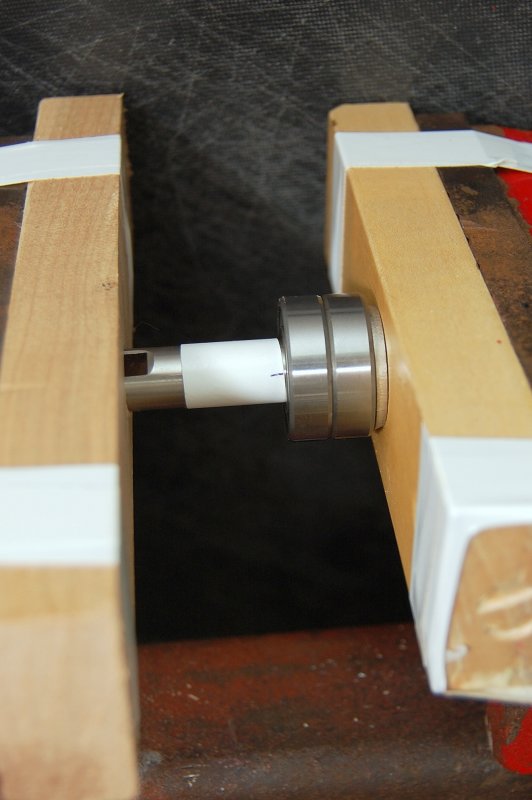
The Bench Vise / Home Made Press
In this picture you can see that I have faced the jaws of my vice with two maple blocks and held them in place with electrical tape. Both wood blocks have holes in them to accept the shaft & keep it in place. The holes and blocks are also centered perfectly over the center line of the vise jaws.
Vises are not the most precision instruments, therefore it is important that you line everything up so the jaws don’t cock-off one way or the other when you tighten down on the shaft & bearings.
The bearings need to press on at a perfect 90 degree angle to the shaft, or they won’t.
If you look closely you can see the pressing washer.
Depth Check
Here I am comparing the old shaft & bearings to the new one.
IMPORTANT: The bearings MUST be pressed on from the opposite side of the shaft from the water & oil seals. For this pump it means the bearings are pressed on from the engine side. If you press the bearings on over the shaft, from the impeller end, you can mar the surface which will in turn ruin the new seal and you’ll have water and oil leaks.
TIP: Please do not over-press your bearings. The oil seal is very close to the bearings and if you press the bearings beyond where they need to be, you will have just ruined your new shaft. Do not skip the depth marking and measurement steps.
Install The New Shaft & Bearings
Just like you removed it you can re-install it with a block of wood and a hammer. Please be careful to make sure your bearings & shaft are 90 degrees to the base of the pump before tapping them home. You do not want to try and tap them in crooked.
If your bearing press-fit into the pump housing is tight you will want to come up with a way to press on the outer bearing races that meet the pump body. This takes the pressure off the bearings and inner bearing race. This pump was not a horribly tight fit, so the block of wood worked fine.
Press In The Oil Seal
I used this nylon washer with a socket to apply an even pressure to the oil seal when seating it into the pump body. It is just slightly smaller than the seal itself. I used nylon to prevent marring the pump body. If you were to scratch these inner walls water or oil would have a way around the seal via the scratch.
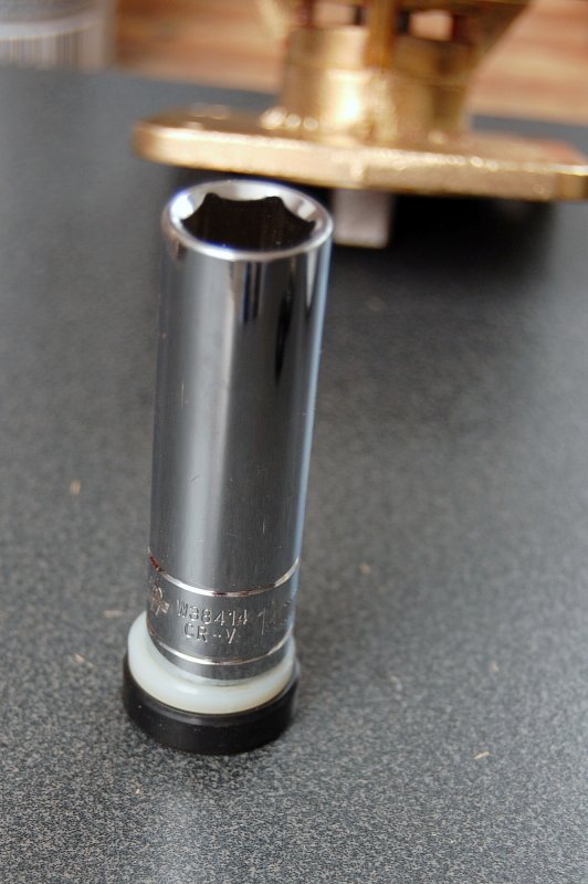
The Socket, Washer & Oil Seal
This is what I use to press the oil seal into the pump body with. When pressing in the oil seal DO NOT drive it all the way in. Press it in so it is just slightly proud of the weep hole. The spacer and water seal, when pressed in on top of it, will seat it to the proper depth so it does not interfere with the bearings. You can over-seat the oil seal if not careful and reversing an over-seating of the seal is not easy.
Pressing In the Oil Seal
Here is the socket with nylon washer I used for pressing in the oil seal.
Oil Seal Seated
If you click on this image and blow it up you’ll notice some red paint. This paint is the weep hole. The oil seal is just slightly proud of the weep hole so when the water seal and spacer are installed on top it gets seated to the precise depth needed without impinging upon the bearings.
Before sliding the seal over the shaft it’s a good idea to pre-lube it with some motor oil. I usually just tip a bottle of oil over, then right side up again, quickly and with the cap on, and this leaves enough oil on the underside of the cap to dip your finger into.
Before installing the pump on the motor it would be a good idea to squirt a little oil into the bearings with the pump sitting on its face. Gravity will bring the oil to the seal. Doing this will pre-lube it prior to installation. I would advise draining this oil though before installing it. This will prevent getting oil on the gasket. All you need is a surface film of oil to prevent a dry start.
Pressing In The Water Seal
As you can see I am using a socket that fits just inside the metal seal cap of the water seal. This worked very well for seating the water seal.

Spacer / Weep Hole
If you blow this one up and look carefully you can see one of the spacer feet. This photo should explain why the spacer is important. It keeps the two seals apart to prevent a water side leak from getting into your engine oil.
Install The C-Clip
Just as you removed it, reinstall the c-clip or retaining ring.

Install The Impeller
When you install the impeller it is important to apply a liberal amount of Glycerin or “Impeller Lube” to the pump body and the impeller.
TIPS:
1- Glycerin can be purchased at any drug store for far less than it is sold as “impeller lube“.
2- Contrary to the myths about aligning the impeller vanes in a certain direction, it really does not matter. Just squish them and install the impeller, they will orient where they want to be the second you hit the starter button.
WARNING: It is not advised to use petroleum based lube products on impellers as these greases or oils can damage and shorten the life of the impellers rubber compound. Lube with glycerin.
Apply the Gasket
These cheap paper gaskets tend to suck donkey balls. (grin)
To aid the gasket in making a good seal I use HondaBond 4 (do not confuse HondaBond 4 with HondaBond HT which is silicone).
Personally I do not like silicone gasket maker and much prefer products like HondaBond 4, YamaBond or ThreeBond 1104. A product called The Right Stuff from Permatex is also similar. These sealants do not totally cure, remain flexible and will not contaminate sealing surfaces with silicone.
Do not over apply any gasket sealer. You only need enough to have skim coat on the surfaces.


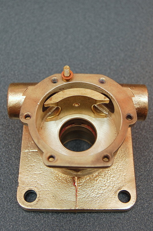
All Done !
The pump is ready for paint & then for use.
Good luck & happy boating!