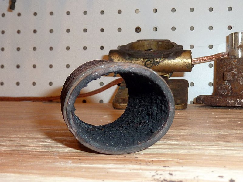
After Cutlass Bearing Removed
I get lots of comments to the effect that I make these jobs look too easy. They are easy, it does not however mean they don’t get frustrating. I wanted to use this post to assure readers that I face the same obstacles as everyone when working on boats. This post will give you a good understanding of how boat jobs often go, with one problem leading to, or unmasking yet another problem. I call it the snowball effect.
The Snowball Effect:
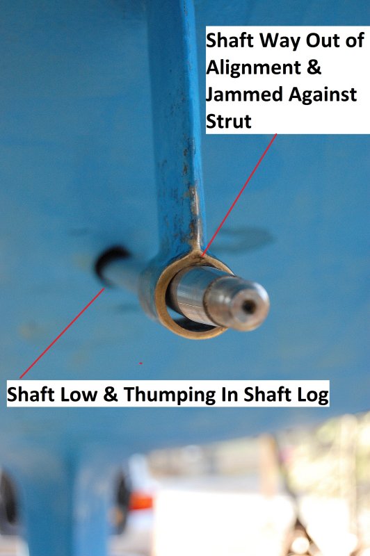
This job was to be a simple shaft, cutlass, coupling & prop replacement but oh how things change when you get going. The boat, a mid eighties Ericson 34, had relatively low engine hours for her age but exhibited a very high level of vibration. After I pressed out the cutlass bearing it became very apparent just how badly the vessel was misaligned.
Not only was the engine sitting far to low in the shaft log, and the shaft was thumping it when the engine was in gear, it was also not passing through either the shaft log or the cutlass anywhere close to parallel. The minute the cutlass was pressed out the shaft sprang up and pressed itself into the top of the strut.
While boats can lose some alignment out of water, it is usually in the order of thousandths of an inch when measured at the shaft coupling. My own CS looses about .001″ from in water to out of water in terms of alignment, and she has a longer shaft. This boat has a fairly short shaft and robust engine bed area so hull-flex was not causing this level of alignment issue. Read on and you’ll find out the real reason this motor was so badly aligned.
The Snowball Starts Rolling – Failure Mode 1
When we got the new shaft in place I wanted to adjust the engine first, to do a rough alignment. Ericson, in all their infinite engineering wisdom. chose a three point motor mount system for the Universal M-25 diesel. Three motor mounts is not the norm in boat building and almost all engine manufacturers ship engines with four mounts, generally with very good reason.
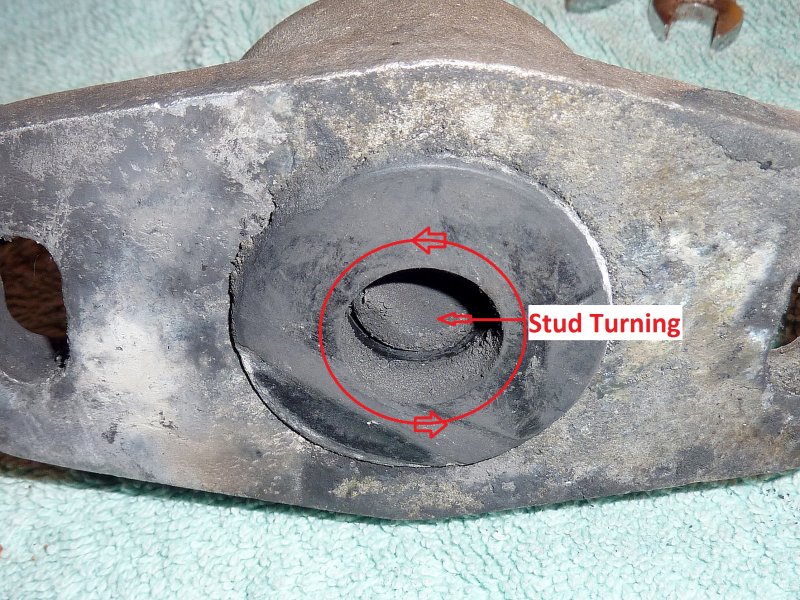
The minute I put a wrench to the front mount, in order to adjust it, and thus drop the shaft from impinging on the top of the strut, the motor mount stud began to spin in the mount. In the marine environment these studs can get rusty, or in this case, the threads also get mashed and the stud with this type of design breaks free from the rubber it was molded into. In my opinion & experience this type of motor mount is just a bad design choice for use on boats. It became clear very quickly the boat needed at least one new mount but I advised the owner to install three new mounts. With a three point motor mount design, or even a four point design, mixing old and new mounts is just a poor choice.
Failure Mode 2
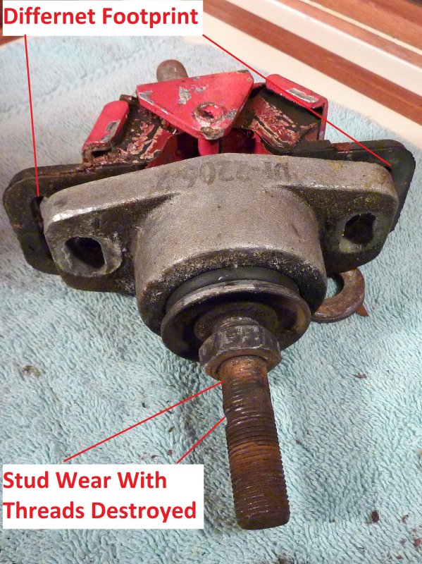
One thing I often see that destroys motor mounts prematurely is the lack of properly tightening the stud nuts that clamp the motor mount bracket. If these nuts are allowed to become loose the motor mount bracket or bell housing ears will vibrate over the threads and wear them away to nothing. All three of the mounts on this Ericson 34 had badly worn threads.
Worn threads will prevent any future re-alignment and require new mounts whether the rubber is ready to be replaced or not. One of the mounts was still in operable condition, had the threads not been destroyed by letting the nuts come loose. The other two were toast and both spinning in the rubber.
Unfortunately in order to replace these mounts with a different model or brand would have entailed a far more costly and time consuming job due to differing bolt centers for the mounts. The three point design of the Ericson motor configuration is dependent on the rather stiff lateral design of these mounts. It was decided, though not happily, to re-place these mounts with the same brand & model despite their many short comings..
Failure Mode 3 – The Snowball Gathers Speed
Yes, this simple shaft & cutlass replacement turned into a total comedy of errors. This was the starboard rear motor mount. It had been broken for quite some time as evidenced by the mushrooming of the sheared stud. With one failed mount, in a three point Ericson design, you are now left with just two rather unsuitably designed motor mounts holding a 350+ pound engine in place. Scary stuff for sure…
If there had been four mounts, and one broke, this is not as big a deal & you’d be back to what Ericson used every day, just three, but with just three motor mounts…well… it is what it is.
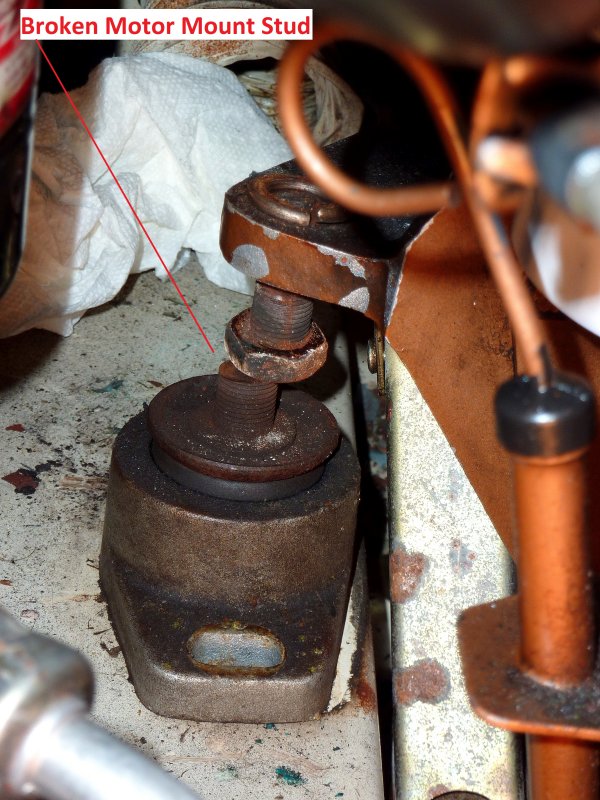
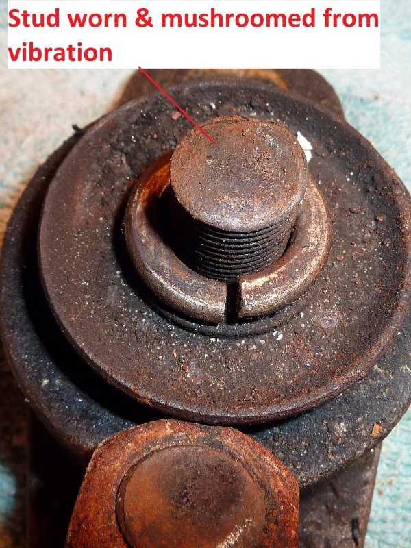
Sheared Motor Mount
This was the sheared motor mount stud. It had obviously been broken for a while as evidenced by the mushrooming of the stud. Broken mounts are not all that uncommon in Maine. We have lobster traps to snag a motor and stall it abruptly, by tangling the prop, as well as lost of floating debris, such as polypropylene line, dragged off 3000+ miles of shore line during spring tides. In short shaft, prop, reversing gear and motor mount damage is not all that uncommon in these waters.
Sometimes the shaft bends or breaks, sometimes the prop, sometimes the gear box fails and sometimes a mount fails. I can’t say what caused this mount to shear but I can say having only two mounts left, when one fails, is a little unsettling.
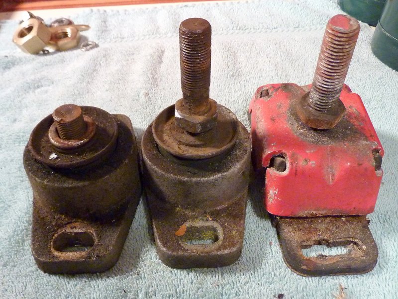
Motor Mounts
The red mount on the right is an older style Westerbeke/Universal factory motor mount. They are well designed, robust and do a very good job of isolating vibrations despite their rather expensive price tag. That red one had 2782 hours on it and the two failed mounts to the left are low hour mounts that had already been replaced once before.
There are features of the Westerbeke/Universal mount that make them well worth the money:
1- You can’t physically twist the stud inside the mount because it is welded directly to the mount cap.
2- The feet are encapsulated in molded rubber helping to minimize noise and vibration transmission to the hull.
3- The metal cap prevents engine oils from eating away at the rubber by shielding it.
4- The mount is fail safe and designed to survive an inversion of the boat without the motor separating from the mounts.
In short I am not a big fan of the two mounts to the left and I have seen the same type of failures repeated prematurely a number of times.
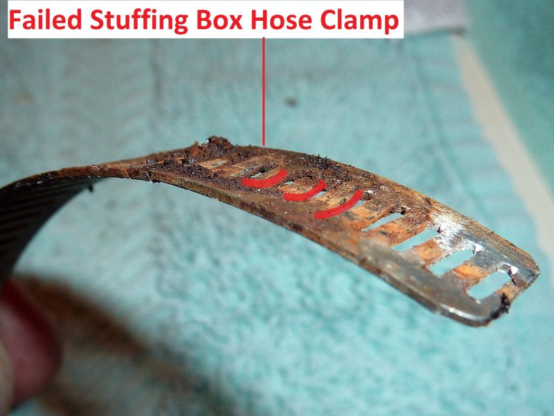
Oh & Failed Hose Clamps Too..
The snowball just keeps getting bigger and bigger.. I’m not kidding, and yes this comedy just keeps getting better, or worse, depending upon how you look at it. This picture is one darn good reason why I detest Ideal style or perforated hose clamps. This was the hose clamp for the stuffing box hose. Two out of the four literally fell apart the minute I touched the screw driver to them.
Because the perforations make the center of the clamp softer than the edges, due to the removed metal for the perforations, they can bend upwards and away from the screw threads over time. The screw on this perforated hose clamp one literally fell out of the holder and yes, they were marked “all stainless”. These hose clamps were keeping this boat afloat and thank God there were four.
Please consider the use of non-perforated hose clamps for your below water connections. I prefer the AWAB brand and have never once had one fail. I have seen literal buckets full of the perforated style hose clamp fail.
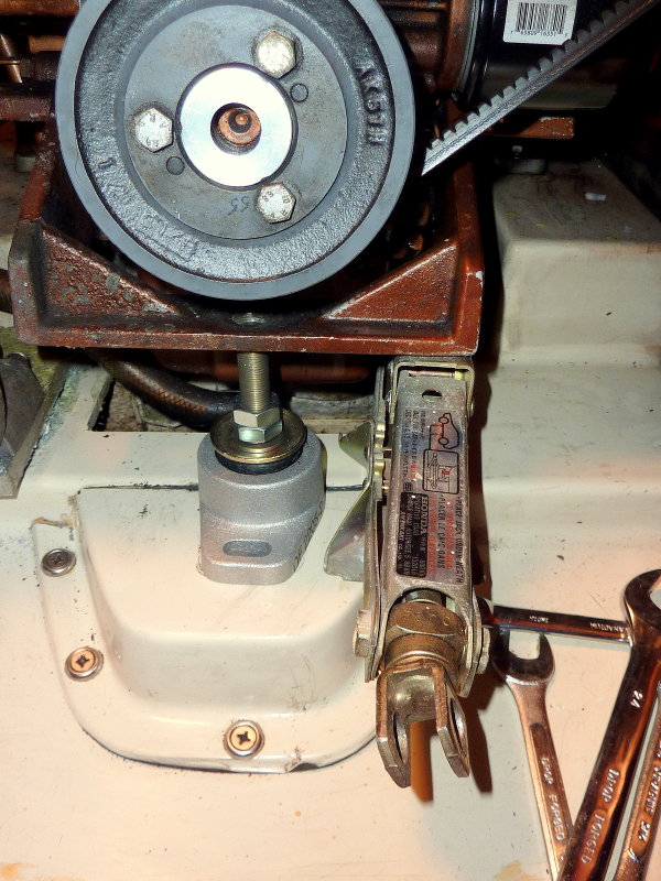
Replacing A Mount
To make this task easier I use my favorite scissor jack. This jack came from a Honda CRX I owned in high school. I loved it so much I kept it when I sold the car to the scrap yard. This little jack folds to about 2″ tall making it easy to slide under even the lowest motors. These can be found in junk yards and will be the best $5.00 you ever spent.
There was yet one more problem with this installation. The stud on this front mount winds up behind the lower crank shaft pulley. When the boat is put in gear and the motor moves slightly forward under load the studs threads grind on the back of the pulley. In order to prevent this the stud needs to be cut shorter to clear the pulley once the engine is in alignment.
When jacking a motor be sure that the shaft coupling, any hoses, refrigeration belts or other items that could impede the raising of the motor are disconnected. You’ll also want to loosen, but not totally remove, the top nuts on the other mounts to facilitate the motor being lifted enough to get the mount out. Removing the old mount and sliding this new one in place took all of about 10 minutes.
Socket Extensions Help
This engine room had very tight access on the starboard side. In order to remove the motor mount lag bolts, I used multiple socket extensions. This made for a quicker and easier job.
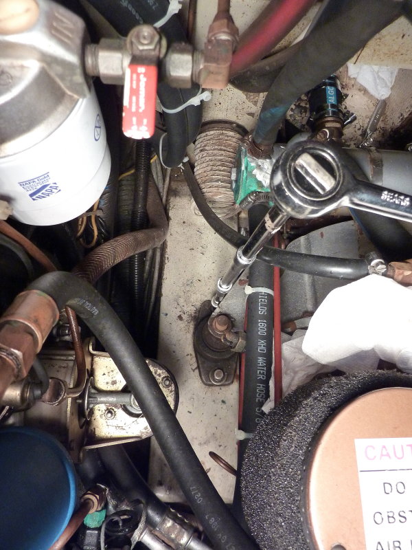
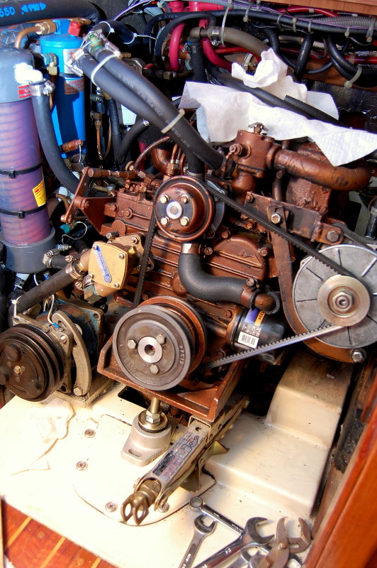
Cramped Engine Room
For a 34 foot sailboat this engine room was rather loaded with gear. She had a Sea Frost engine driven refrigeration system, fuel filters, water heater hoses, upgraded alternator and many other non-standard features that make working in there tight. The small scissor-jack is critical on engines like this when replacing motor mounts.
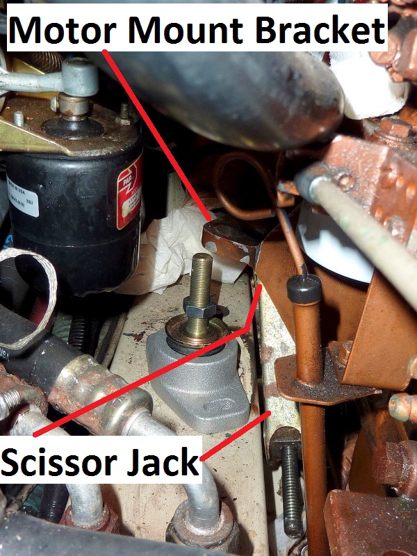
Replacing The Starboard Rear Mount
The camera angle makes this area look a lot more roomy than it really is. The scissor-jack fit quite nicely between the engine bed stringer and the engine. In this image the scissor-jack is lifting in-board of the motor mount hole but using the motor mount bracket to jack the engine. This is a good illustration of why this little jack has stayed in my tool quiver since the mid 80’s..
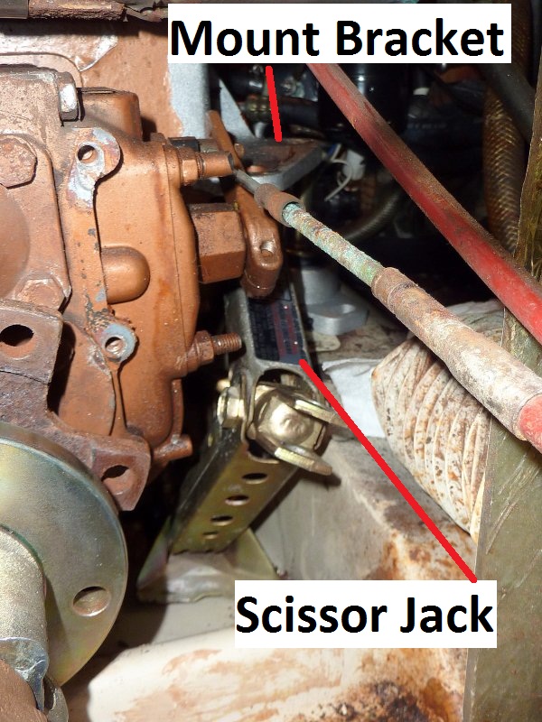
Same Mount Looking Towards The Bow
Here is another shot of the scissor-jack. I collapsed it entirely and slid it in through the transmission opening in the bulkhead. You need to be careful and use mirrors to make sure you are not jacking on the oil pan or any sending units, hoses or fragile brackets. Oil pans can be used on small engines but I would advise using a block of wood to spread the load. If your oil pan is rusty please do not use it or you may punch through. If possible always use the mount or another strongly supported area of the engine.
Lifting one corner of an engine is not a lot of weight. The weight is so little that I can usually twist the jack screw by hand with no extensions or tools. With the other mounts loosened it is very easy to lift one out. If you can get a good jacking angle, and find enough support, you can lift in the center and raise the front or rear and do two front or rear mounts at the same time. What ever works and won’t damage the hull or engine.
Snowball Still Growing….
Yes, believe it or not I discovered yet another problem. Once all the new mounts were in place I began to do a rough alignment of the motor to the shaft, cutlass & shaft log.
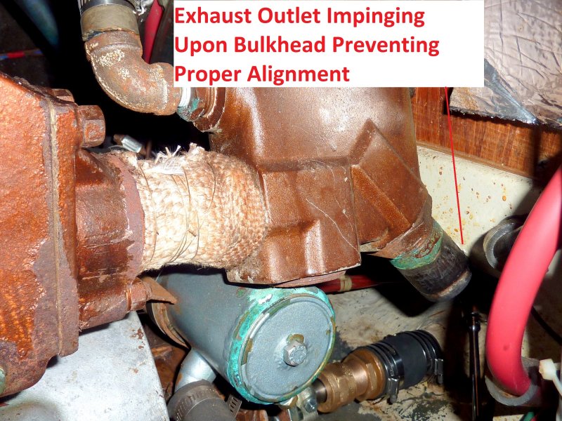
For some reason the I could get close but she just kept popping back out of alignment no matter how I moved the engine. After 20 minutes of mucking with her I realized why the engine was so low to begin with. A previous owner had replaced the exhaust elbow, a whole other set of problems, and made the nipple between the manifold and the exhaust elbow too darn long.
To correct for this mishap they Mickey Moused it by simply lowering the engine so the exhaust outlet cleared the bulkhead. This fixed the exhaust issue but caused many more as you’ll see below.
Ouch, Snowball in the Face !
As I said earlier this entire project has been a complete comedy of errors. Either the previous owner who did all this work was a really lousy DIY guy or he hired the absolute worst marine tech on the planet. There was no reason for this exhaust elbow to be tilted off center other than the fact that the installer refused to use a suitable pipe dope to mate the NPT fittings together.
It likely bound up, when installed dry, and refused to turn anymore so they just left it tilted off center. Due to this laziness, or lack of understanding, it caused the exhaust elbow to chafe, vibrate, dent and make a career ending thin spot in the heat exchanger.
Cha-ching $$$$ more unnecessary expense for the boat owner. Had someone done this job correctly to begin with, the owner would have likely not have needed a new shaft, cutlass, motor mounts, heat exchanger etc. etc. etc…
This manifold will fit and will clear the bulkhead & heat exchanger when installed correctly, it was not. This level of workmanship is really rather disheartening…

More Frustrations
As mentioned the exhaust elbow was a disaster of an installation. Who ever did this install clearly knew nothing about thread sealants or pipe dope. It took nearly four hours of heat, PB Blaster, a massive bench vise and a 3.5 foot 1 1/4″ black iron pipe as added leverage to an 18″ Rigid pipe wrench to break these fittings apart. This is complete insanity.
Due to the improper installation of these threaded fittings they had been leaking since very early on and had physically rusted together as hard as I have seen in a long time. PB Blaster & Kroil are great but when you are dealing with sealing threads, such as NPT, that are meant to keep fluids out, they also tend to keep most of the PB Blaster or Kroil out too.
This exhaust flange fitting is a $90.00 part from Universal so I clearly wanted to save it for the owner.
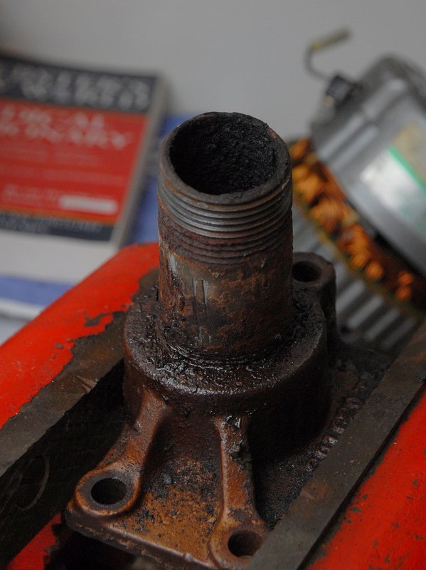
It Was Really Stuck….
After many hours and a very long pipe on the end of a very robust pipe wrench the nipple finally gave up its hold. The force needed to remove it from the exhaust flange crushed the schedule 80 black-pipe and made it oval.
A Lot of force Was Required
This is what my 3.5 foot black-iron pipe looked like after I broke the stuck fittings free. I have not done the calculation on how much force I applied but all my 200+ pounds were going into that leveraged pipe and the fitting was over 4.5 feet away away from the end of the pipe.
IMPORTANT: When putting NPT threaded exhaust fittings together please use a proper high temp rated pipe dope. It will make future repairs significantly easier.
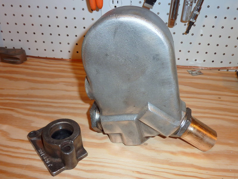
Apart & Cleaned Up
The owner was already into this job for a new shaft, coupling, cutlass bearing, three motor mounts, packing material, stuffing box hose, four AWAB clamps, a heat exchanger plus various nuts bolts and hardware. I really did not want to have him absorb the cost of a new exhaust elbow and flange on top of all this, for just for a few stuck fittings.
This would have been about $300.00 worth of additional parts but I was able to clean, paint and re-use them.
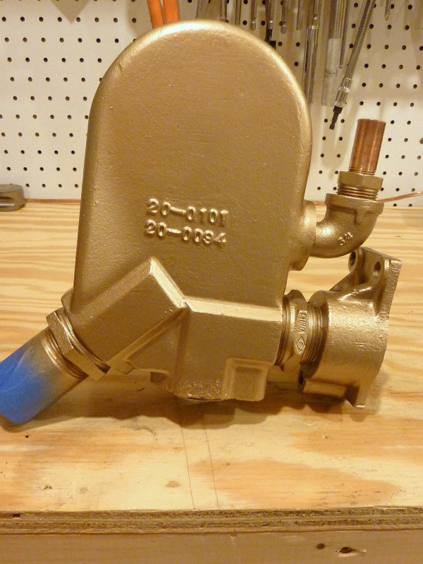
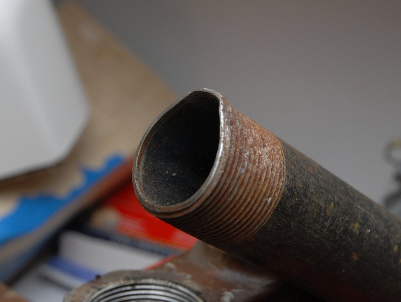
Exhaust Elbow Ready To Reinstall
I was able to take nearly 2″ out of length out of the nipple between the exhaust flange and the exhaust elbow. This allowed the elbow to no longer hit the bulkhead and to also clear the new heat exchanger. I used a *street-elbow for water injection which allowed the assembly to be shortened.
Street-Elbow = Male NPT on one end & female NPT on the other.
This particular exhaust elbow is not a Universal Engines genuine part hence the reducing bushing from 1 1/2″ to 1 1/4″. Gotta love that snowball…..
The motor mounts were actually the easy part of this job. It’s all the little things you find along the way that cause the job take longer and tend to get frustrating. For example, getting the exhaust elbow off the engine required the engine to be completely lifted off the mounts and moved forward. None of this extra work was planned on when we started and most of it could not be identified by a cursory inspection. I used a 4:1 Harken block & tackle rigged to a beam across the companionway for lifting the engine. This little extra step added almost an hour and a half to the job..
Summary:
A simple shaft, folding prop & cutlass replacement led to:
* Three new motor mounts – all failed
* Removal, cleaning, re-plumbing & reconfiguration of the exhaust elbow
* A new heat exchanger
* Failed hose clamps
* Engine antifreeze flush & fill etc.etc..
Believe it or not this really is a more typical job than it would seem. This sort of snowball effect happens quite often with boats and is not really all that uncommon.
The next time you get an unexpectedly large bill, for work done to your boat, remember that this started as a simple shaft, folding prop & cutlass bearing but ended up as much, much more.
Good luck & happy boating!