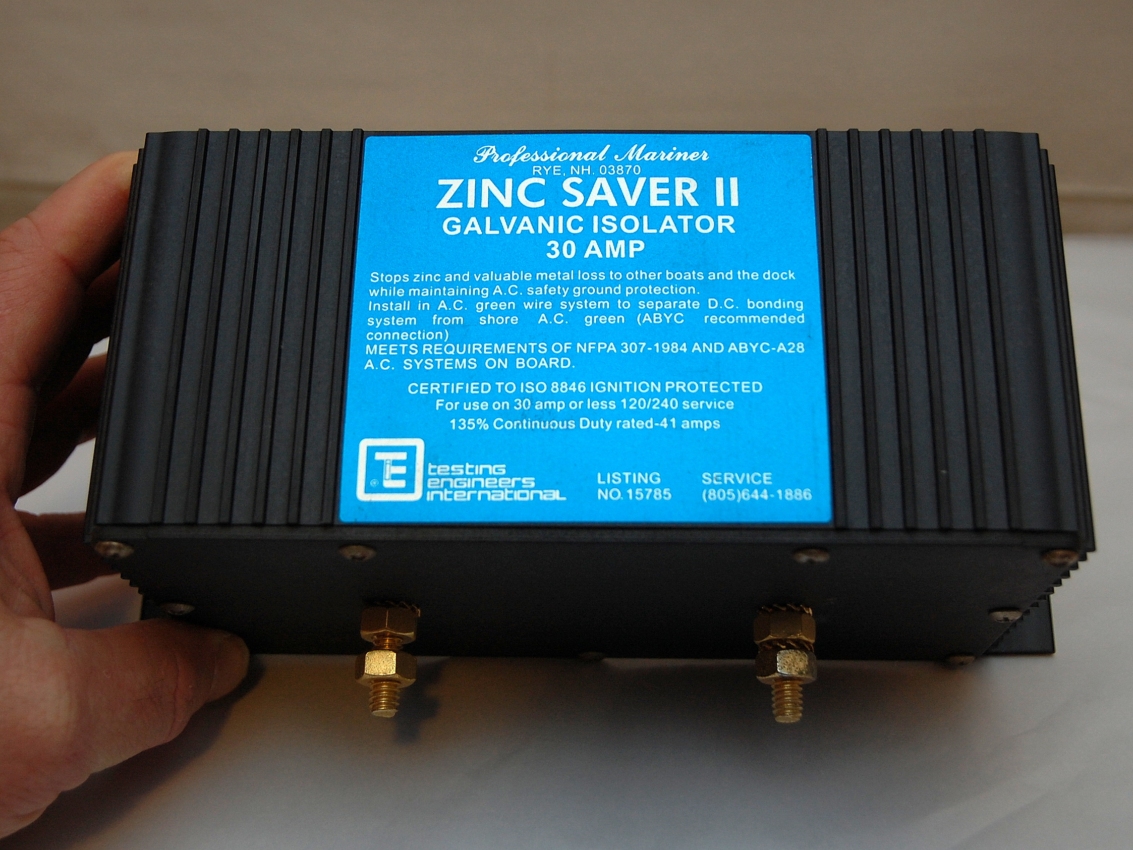
A 30A Galvanic Isolator
WARNING: The galvanic isolator used in this article does not meet the current safety standards. To meet the current safety standards you would need a “Fail Safe” unit that has been tested to the ABYC Fail Safe standards.
The ProMariner ProSafe FS30 & ProMariner ProSafe FS60 both meet the current ABYC Fail Safe standards.Affiliate Disclaimer
Buy Failsafe Galvanic Isolators
Why you’d need a Galvanic Isolator?
What exactly is a Galvanic Isolator (GI), why do you need one & why on Earth would you need to test one? These and other questions will all be answered in this article.
A galvanic isolator is a device that is inserted, in series, into the AC green grounding wire (safety ground) of your shore power feed to help minimize or reduce the effects of galvanic current from flowing into your vessel. While the purpose of the GI is blocking galvanic level current, it also has to allow for the passage of AC fault current. GI’s are a very simple hook up and installation, even for the average DIY, but ensuring you never lose your AC safety grounding conductor is of critical importance.
If plugging in at a marina a GI is a bare minimum level of protection a boat owner should have. Here at Compass Marine Inc. we absolutely prefer an isolation transformer (IT) over a GI but the conversation of a galvanic isolator vs. isolation transformer is a whole other discussion & topic. If you plan to plug into shore power, you’ll need a galvanic isolator at a bare minimum.
To install a GI all one needs to do is to break the green wire, after the shore power inlet, but before the AC panel. Simply cut the AC green wire in two, crimp on two terminals and connect them to each stud. Not many electrical jobs on boats are this simple. As mentioned above the purpose of a GI is to block low voltage galvanic level DC current while still allowing any AC fault current to pass through the green wire to ground and allow it to activate fault protection devices.
This blockage of low voltage DC galvanic level current is achieved by using two diodes in each direction. Each diode drops approximately 0.6V or put another way requires more than 0.6V to open and allow for current to pass. Two diodes in series results in approximately a 1.0V – 1.2V threshold for blocking galvanic level current. The reason for having two diodes, in each direction, is so the green wire is not simply check valved or blocked and acts just like a wire would. In other words it allows fault current to flow through the wire for human safety. The critical difference between a bare green grounding wire is a GI, is the GI won’t allow the passage voltages/current below 1.2V. Simple, and is effective at blocking galvanic level current.
What is Galvanic Current?
The creation of a galvanic current occurs when dissimilar metals, with differing galvanic voltages, are immersed in an electrolyte (water). The more noble metal survives while the less noble metal (anodic) becomes the anode and is eaten away from the galvanic that’s current created by the differences in voltage potential of the different metals. This is why we use what are called anodes to protect our expensive under water metals. Anode materials include Mil-Spec aluminum, zinc or magnesium. These metals serve as the least noble metal in order to sacrifice themselves and protect/save your brass, bronze or other underwater metals from galvanic corrosion.
Metals have voltages?
Yes, each metal has a voltage potential. Data for this can come from any number of Galvanic Series or Galvanic Scale charts. For example a zinc anode can range from -1.00V to -1.07V and graphite, think graphite impregnated packing material or PSS shaft Seals, is upwards of +.2V. It is the difference in electrical potential, when immersed in an electrolyte, that creates the galvanic current that eats away the anodic or least noble metal.
The galvanic series/scale of metals represents a difference in voltage potential, between the most noble of metals (approx +0.2V) and the the most anodic metal (approx -1.4V) of about 1.2V. If you just realized that a GI blocks voltages below 1.2V pat yourself on the back as you now understand what a galvanic isolator is doing.
What is a diode?
Think of a diode as an electrical check valve. A diode allows current to flow in only one direction but not in the other direction. One of the inherent traits of diodes is the voltage drop associated with them, which is usually around 0.6V. In a galvanic isolator application however, they have used this often assumed less desirable trait of a diode to an advantage. By wiring two diodes in series you now have a device that can block any galvanic created current at voltages below 1.2V from flowing into or out of your vessel. The GI blocks galvanic currents from flowing between dissimilar metals and protects you from galvanic level currents in the marina when you plug-in.
Simple Devices
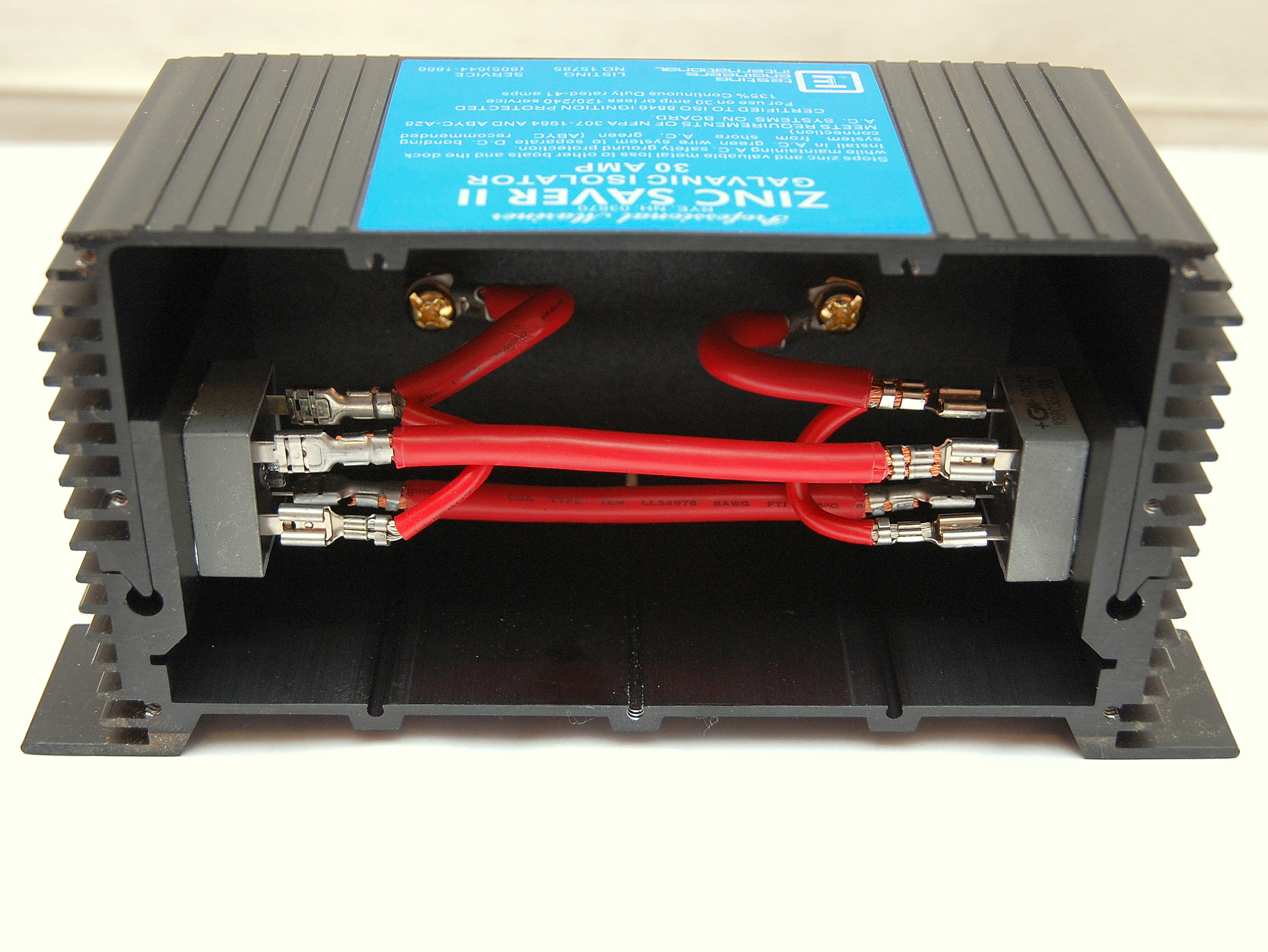
As mentioned above these are simple devices. When opened up you can see just how simple. It is important to note that this particular model no longer meets the current ABYC safety standards. I will get why in a moment. On the back wall we can see the two wires going to the gold plated studs. This is where your green grounding wire would be cut and connected to. Inside we can see the two diodes which allow current to flow in both directions but at the same time blocking voltages below 1.0 – 1.2V.
So why do I need to test my GI?
Remember in the last paragraph when I mentioned this particular GI no longer meets the current ABYC safety standards? Well,there is a very good reason for that.
Think back to when I described where a GI gets installed? It is inserted in the GREEN SAFETY GROUND WIRE. What happens if one or both of those diodes gets blown? You guessed it, you now have no NO SAFETY GROUND. Over the years there were far to many incidences of boats, with GI’s, that completely lost their safety ground connection to shore due to failed diodes.
A single lightning strike on a boat a few docks away could take out half the GI’s in the whole marina and folks rarely even noticed. Honestly ask yourself when you ever heard of someone testing a GI? Right, you’ve most likely not. Couple this with the fact that many more boats are not wired, on-board, to current safety standards where the AC green/grounding wire is bonded to the ships DC grounding bus and this means metallic parts of AC devices could become “hot” in the event of a fault. Hot cases and metallic parts of your boat spell the potential for electrocution or death to occupants or to swimmers by electric shock drowning. Without the safety ground connection to shore the fault protection devices will not trip as they should. This = BAD/DANGEROUS
Below is a direct quote from Captain David Rifkin. David is perhaps the leading expert in marine electrical shock drowning deaths, bonding and corrosion.
“In the many boats I have tested with galvanic isolators, approximately 5% tested open circuited (meaning the boat did not have a connection to the marina grounding system) and the operators were completely unaware.”
I know 5% of the boats with GI’s, and an open circuited ground, does not sound like much, but consider that with the millions of boats in the water there are potentially hundreds of thousands of GI’s installed on boats. How many boats in your marina? 100? So if 5 of those boats are completely lacking a green safety ground wire, do you want to go swimming in your marina? Course we all know we should never swim in a marina, but it happens.
What does meet the current safety standards for GI’s?
The ABYC standards for galvanic isolators have changed a few times over the years. The first iteration required “active monitoring“. This was in the form of a remote lighted panel so an owner could glance over and know they had a safe and operational GI with the safety ground intact. This “active monitoring” added significantly to the cost of GI’s and was a total PITA in terms of parasitic loads because it had to be “wired in” to more than just the green wire. It also created an issue with ELCI’s and GFCI’s as it “pulsed” the safety ground which could cause nuisance tripping.
A number of years ago a company called Dairyland Electrical Industries, or DEI for short, invented/brought the “fail safe” galvanic isolator to the marine market. This advancement brought simplicity, and no monitoring, back to the GI and did away with the idiot lights and related circuitry. Unlike traditional diodes that tend to fail open the fail safely diodes fail closed and all you lose is galvanic protection. Today the ABYC standards require the use of Fail Safe galvanic isolators such as the ProMariner ProSafe FS30 or the ProMariner ProSafe FS60.
The designation FS or fail safe means that these devices fail closed instead of open as a normal diode would. By failing closed you only lose galvanic protection but not your SAFETY GROUND to shore. According to Henry T., one of the owners of DEI, they have not had a single failure of a DEI Fail Safe galvanic isolator where it failed “open”, even to lightning strikes. A pretty impressive feat considering the number of failures that occurred with the older technology, like the one you see here. The results for the ProMariner’s mentioned above are the same, no known unsafe failures.
Today companies such as ProMariner & DEI both make ABYC compliant galvanic isolators with the fail safe technology. Yandina & Sterling Power also make GI’s (we are a Sterling Power Dealer) but they do not meet the current ABYC safety standards so we do not sell nor do we install them. I do mention both of these products though because both companies are at least 100% honest that the product does not meet the current US safety standards. Kudos to Yandina & Sterling Power for being honest in a world of BS marketing hype.
If you’re a mooring sailor who rarely stays at a dock the Yandina GI or Sterling Power GI can represent a value purchase but they must be routinely tested. If adding a GI, for regular dock side use, we strongly advise installing a fail safe product.
How To Test
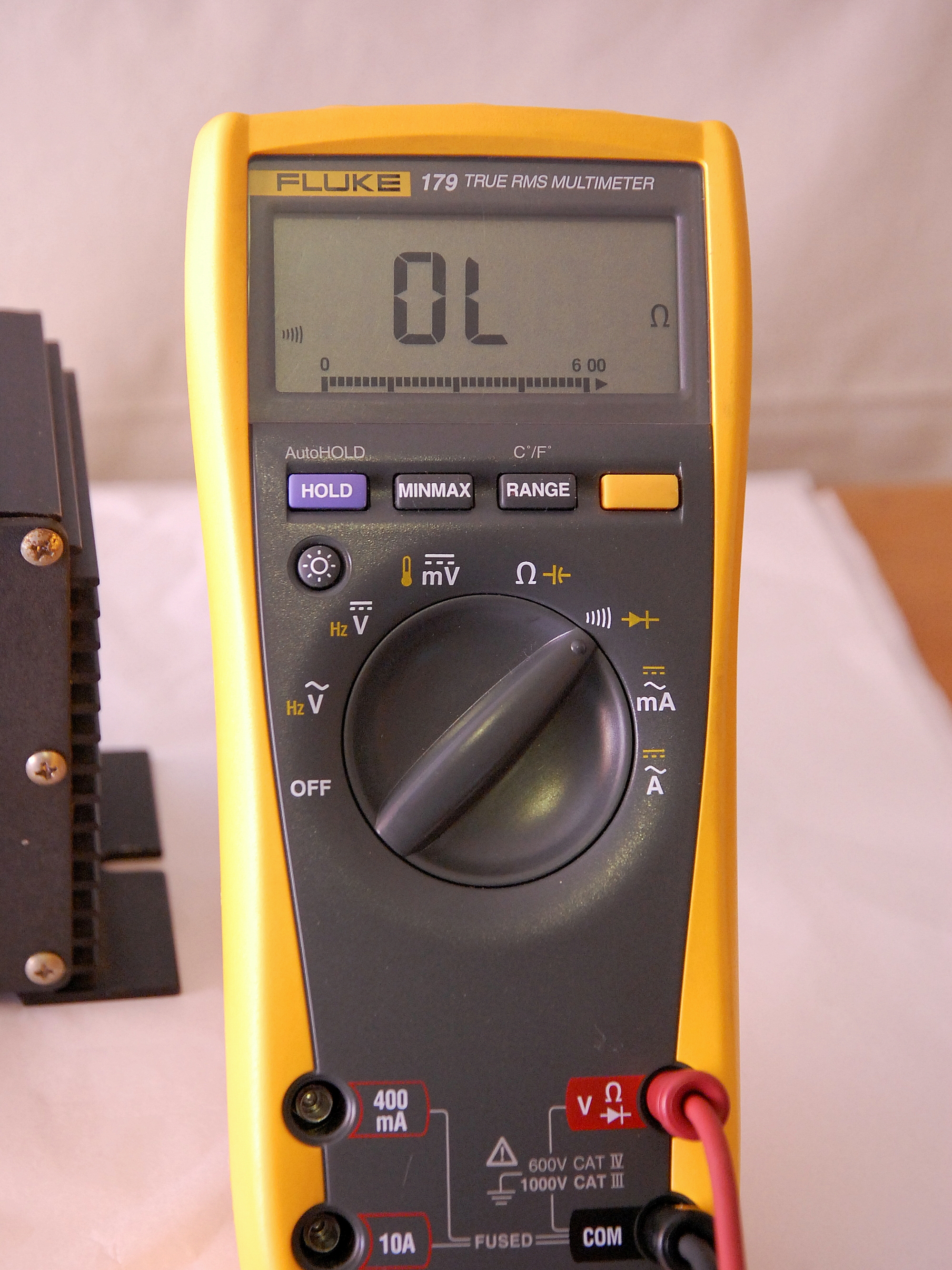
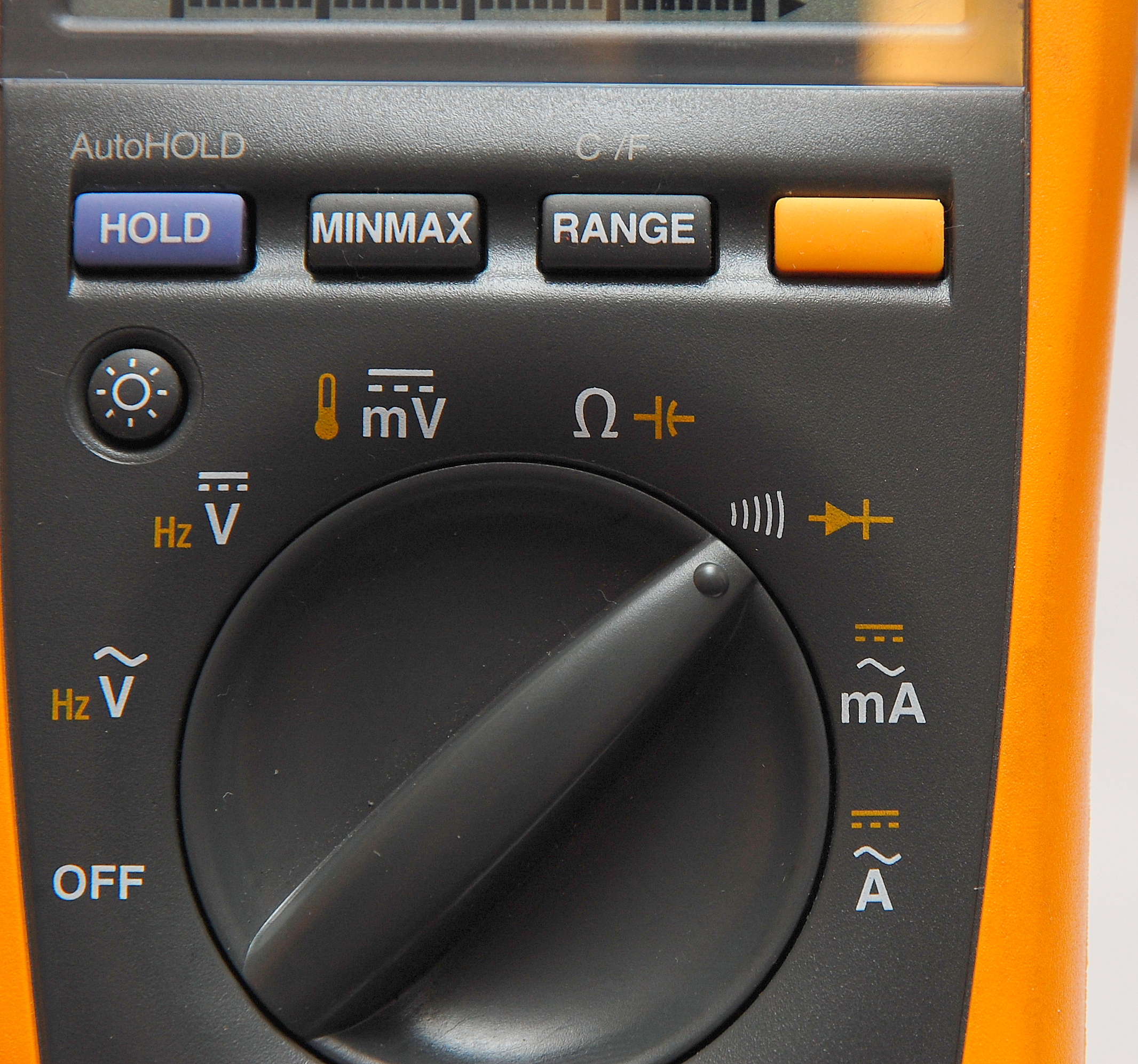
Switching To Diode Test
With this meter pressing the yellow button moves it from the Ω test to the diode test feature. The diode symbol can be seen on the left hand side of the meters screen.
*Connect Your Test Leads

*UNPLUG YOUR VESSEL FROM AC POWER BEFORE TESTING
With the AC power to the vessel OFF/Physically Unplugged, check your inverter too, disconnect both green wires from the GI and connect your DVM leads to the studs.
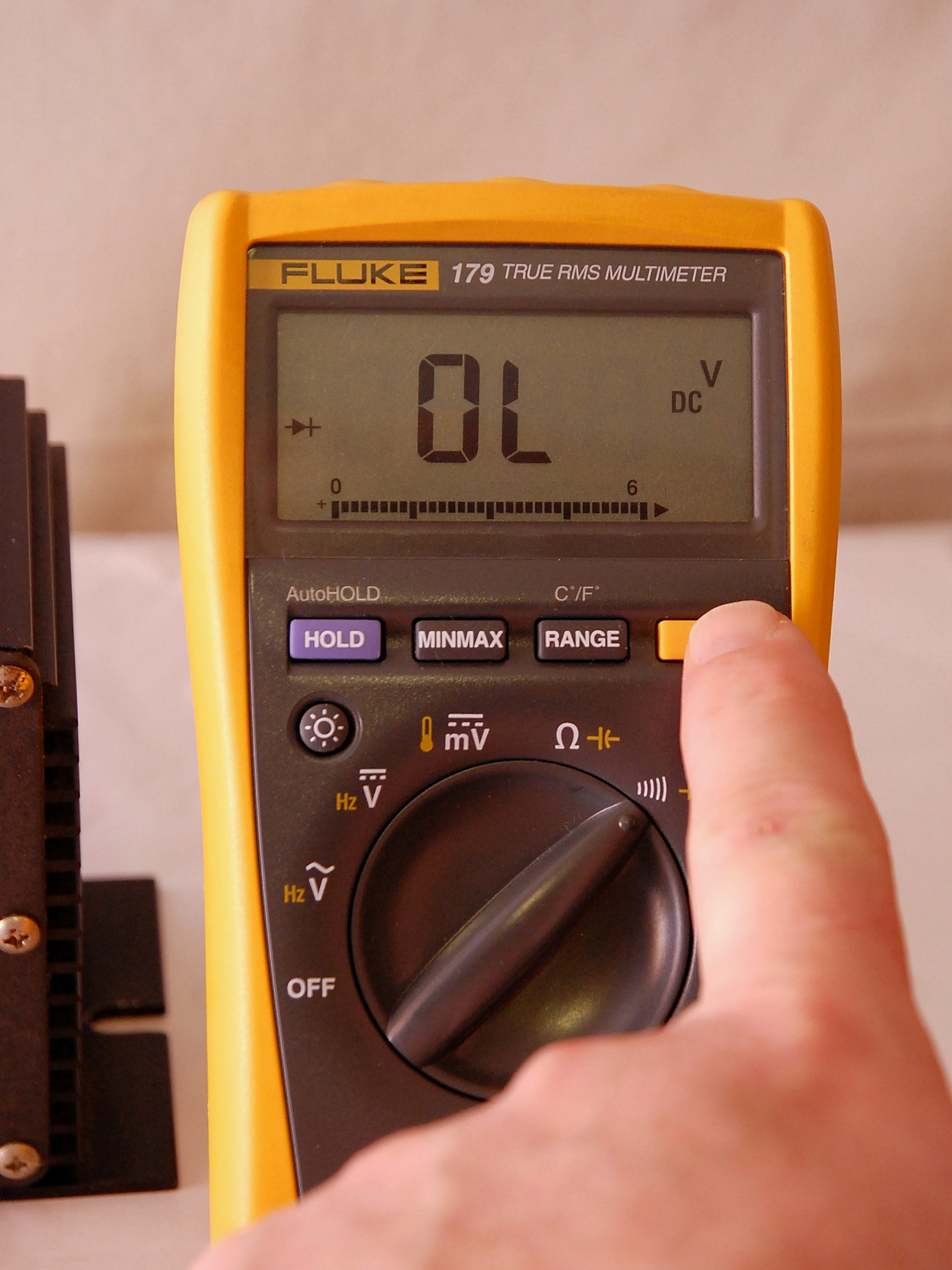
If the diodes are working you should see a reading of .8 to 1.0. here the reading is .973. If the diodes are bad you will not get a reading or will get the OL message (open leads) if using a Fluke. Older style galvanic isolators like this fail open.
Now Reverse The Leads
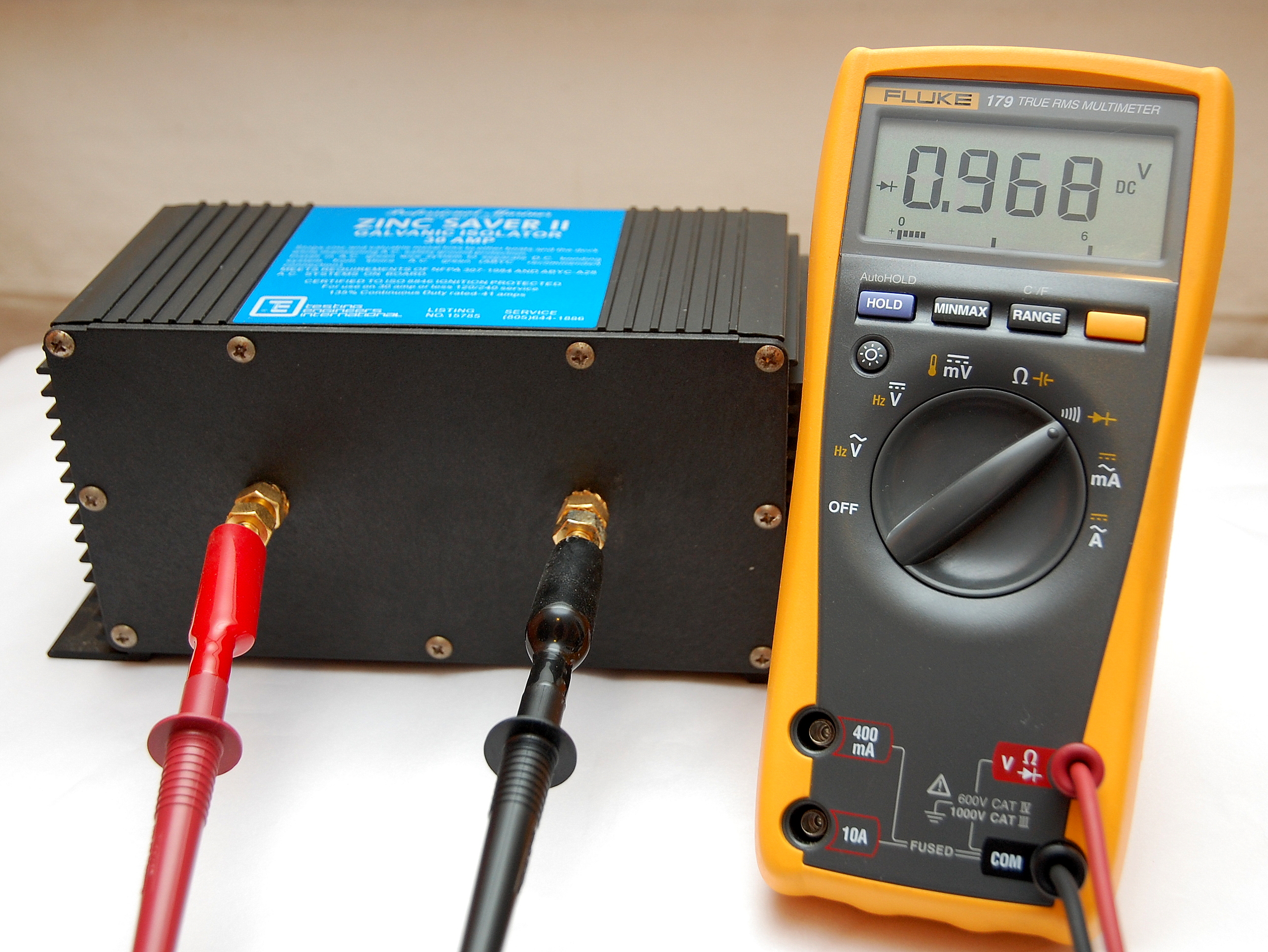
Remember, the current needs to be able to flow in both directions, just like a piece of wire, and it is possible for one side to be blown and the other side still be fine.
Here the reading is .968 and well within range. You are allowed roughly a 10% variance from one side to the other so .968 and .973 are well within that spec at a 0.5% variance. Despite being a relic from days past, this isolator is still operable.
If however you have an old isolator like this, and you keep your boat at a marina, I would strongly advise upgrading it to newer ABYC compliant fail-safe unit. The only other alternative is to regularly test your GI to ensure it is operational.
Our preference for GI’s are the DEI or ProMariner Fail-Safe galvanic isolators. We offer the ProMariner Fail Safe’s, to our readers, in the MarineHowTo.com Web Store.
You Don’t Need A Fancy or $$$ Meter
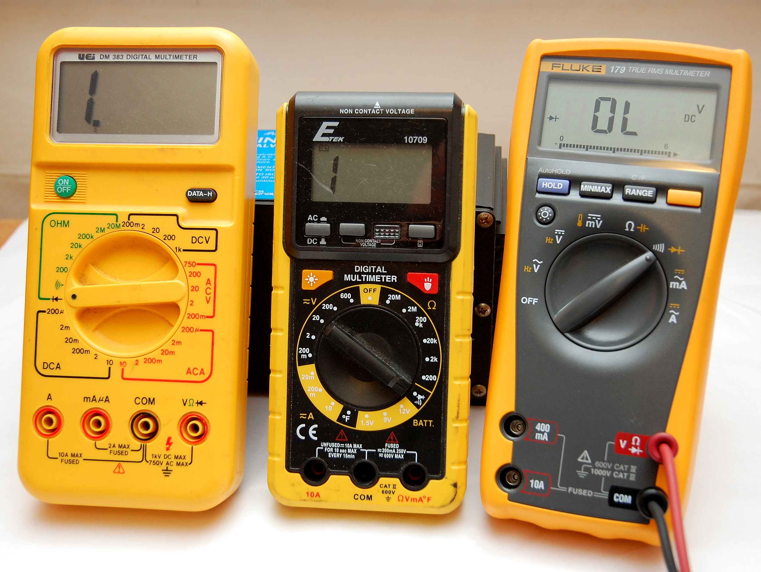
I certainly love our Fluke test equipment, we abuse the living snot out of it, and it survives. However, for a DIY, especially one on a budget, even an inexpensive meter will do. You just need to ensure it has a diode test function. Many “el-cheapo’s” do. Heck, the one in the middle is from Wal*Mart and costs less than a 12 pack of Bud Light.
In this photo each meter has been set to the diode test function.
The Diode Symbol
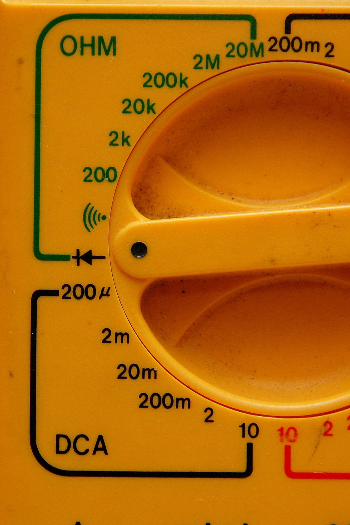
Set To Diode Test
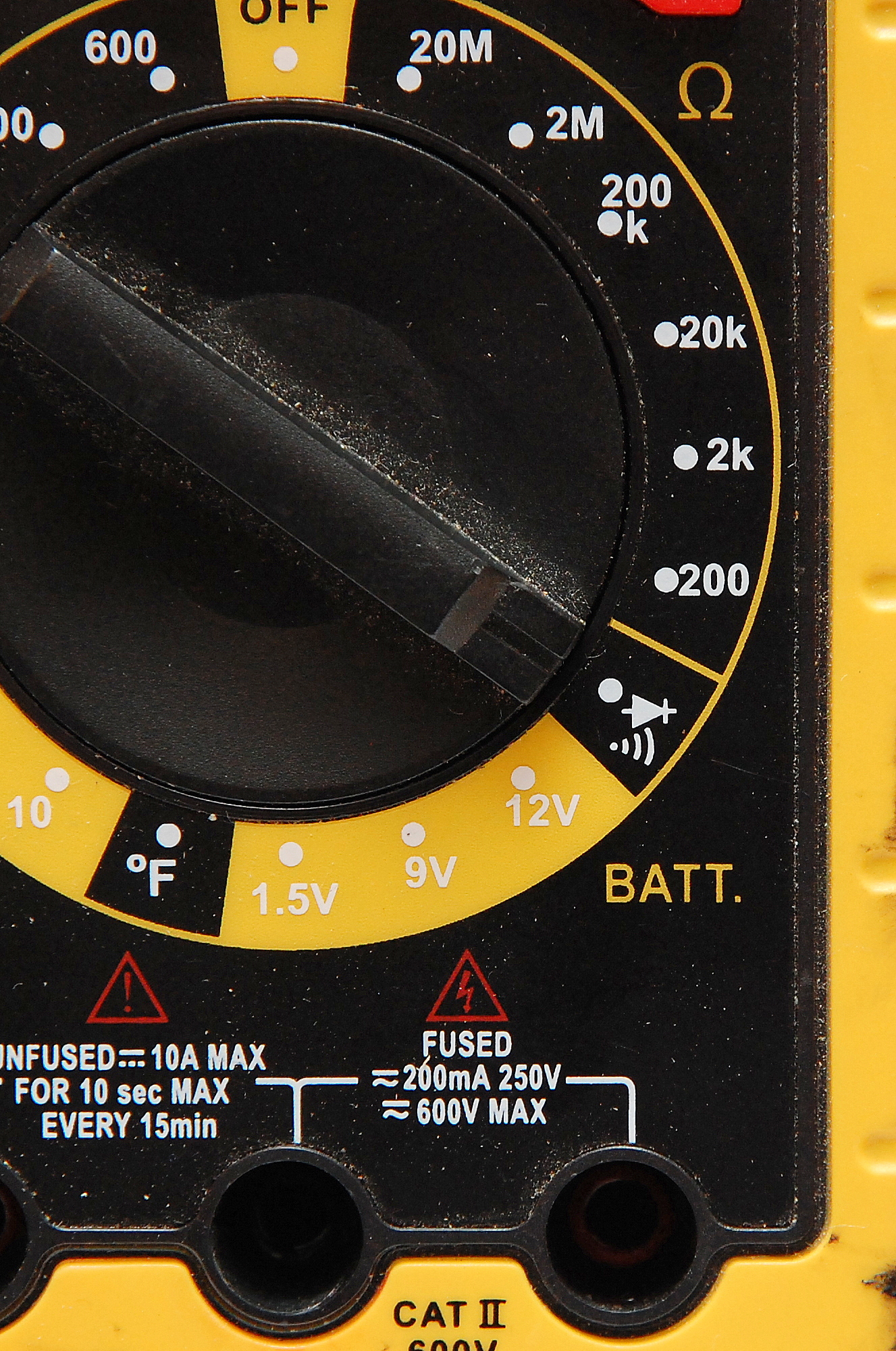
On this meter the diode test function shares a dial position with the audible tone continuity test. This meter was about $14.00 at Wal*Mart.
Diode Test
On the Fluke 179 you simply toggle between the diode test and Ω with the yellow button. When in doubt pull out the manual for your meter.
Alternative Test
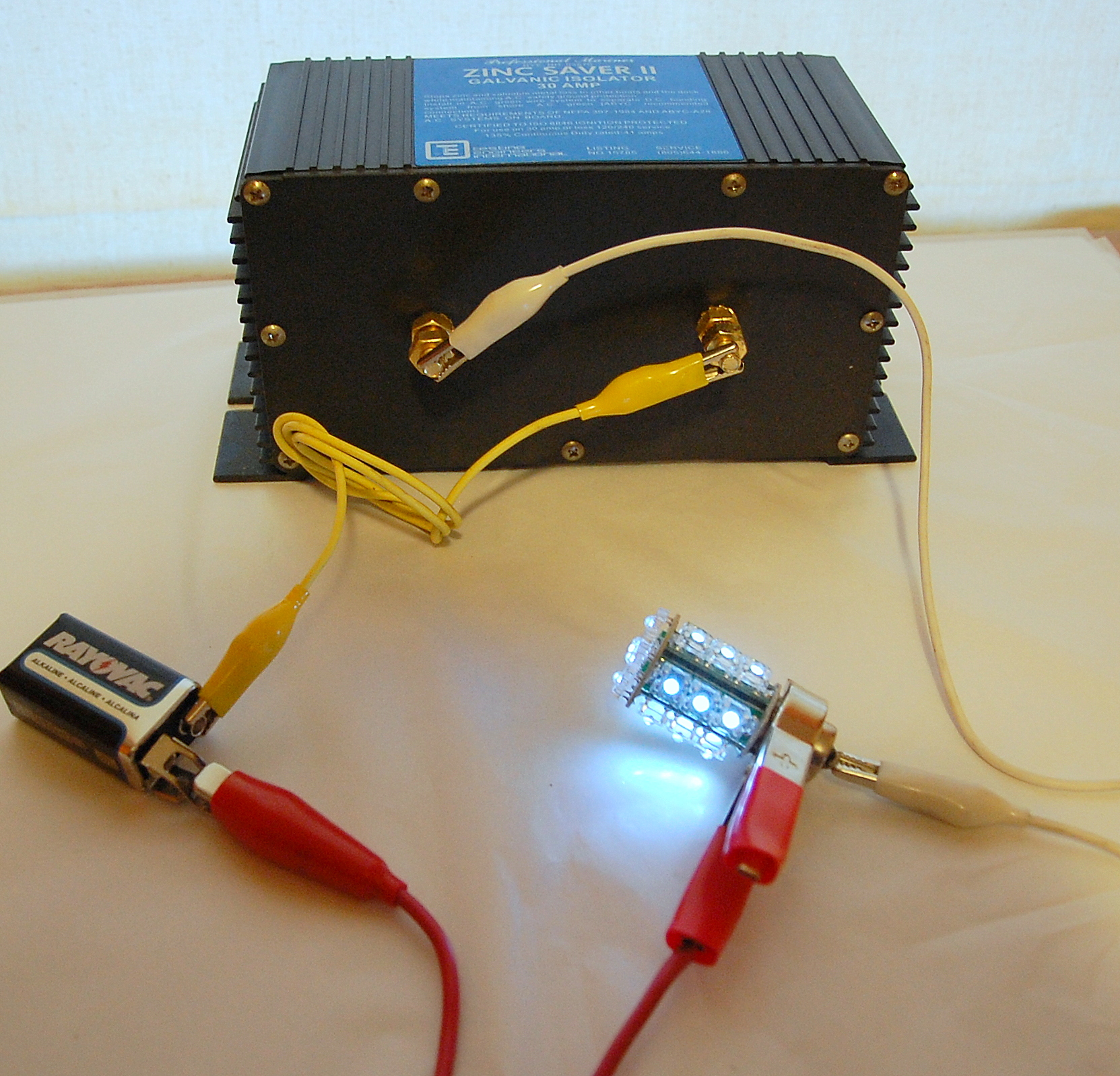
While you’d be best to use the diode test functionality of a DVM, you can do a quick and dirty test with a 9V battery and a 12V light bulb. I don’t recommend using an LED bulb for this test. I grabbed an LED bulb only because it showed up better in pictures. You will get a dimly lit 12V bulb with a 9V battery but the test works.
If you first connect your bulb direct to the 9V battery then test it through the isolator you will notice a change in brightness. This is caused by the voltage drop across the diodes and is 100% normal and should be expected.
Wire the 9V battery and incandescent light bulb as shown (not an LED) and the bulb should light if the diodes are good.
Reverse The Leads
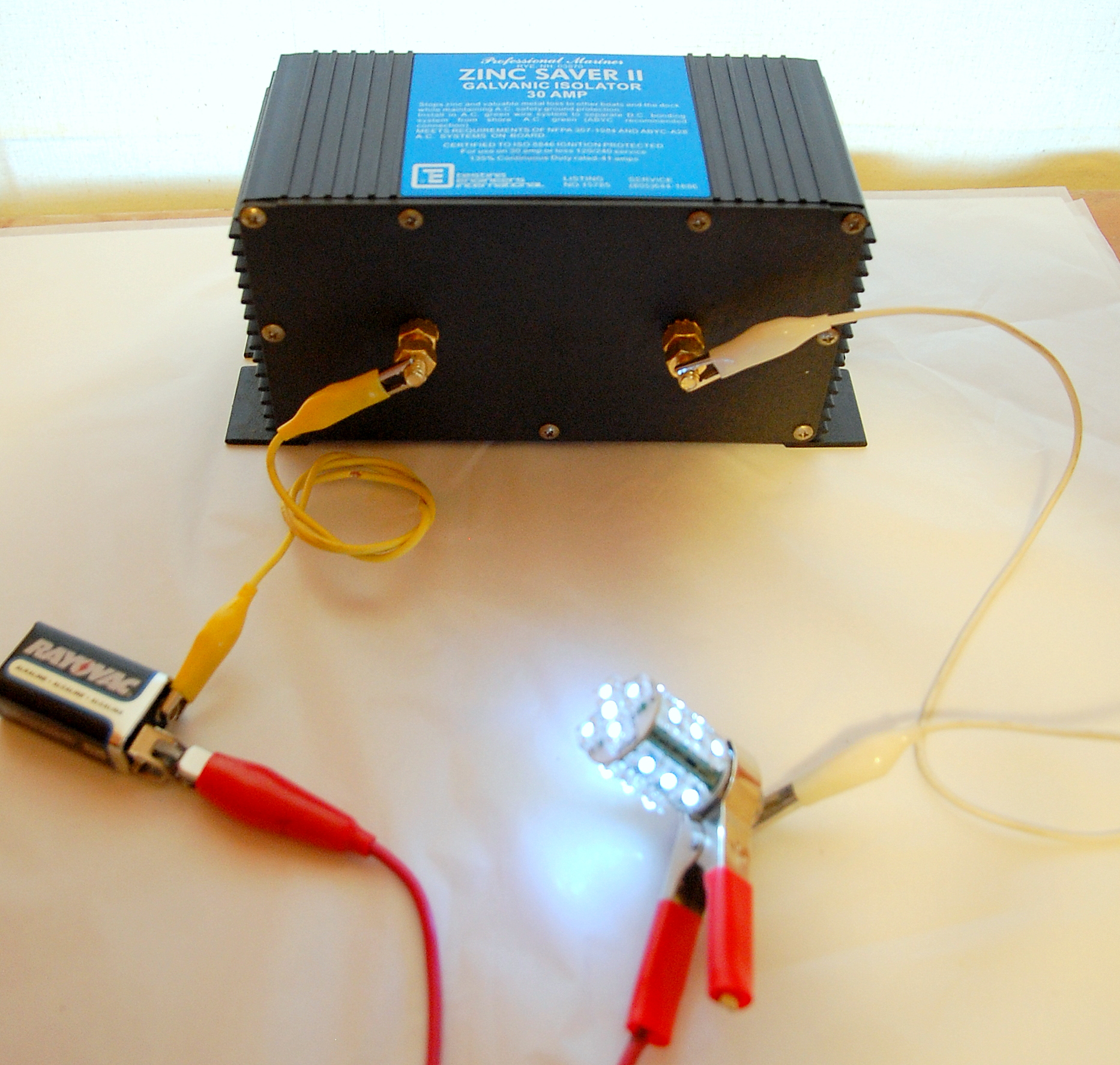
Again, just like with the diode test function on the DVM, you’ll need to reverse the leads to check the flow in the opposite direction. The bulb should light.
Newer GI’s have a remote panel display, that tell you it is on & working, or they are fail-safe so there is much less need to worry about losing the safety ground and really no real need to test them.
This test procedure is for older style GI’s similar to the one pictured. There are still perhaps hundreds of thousands of boats with this style GI installed on-board.
Blocking Current @ 1.1V
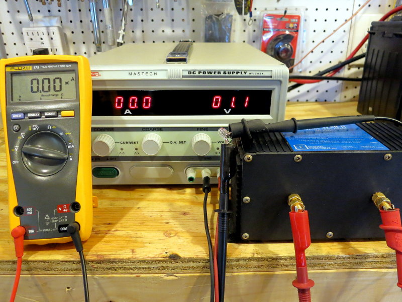
This is a test most owners won’t be able to conduct, unless you have an adjustable bench top DC power supply or a 1.5V battery and some diodes to drop the current below 1.1V.
In this photo I’ve set the power supply to 1.1V DC and am measuring the current with the Fluke meter. As we can see, based on the Fluke meter, the diodes in the Galvanic Isolator are doing what they are intended to do, block DC current to 1.1V.. The Fluke reads 0.00A DC and this is how it should perform.
Current Flowing @ 1.3V
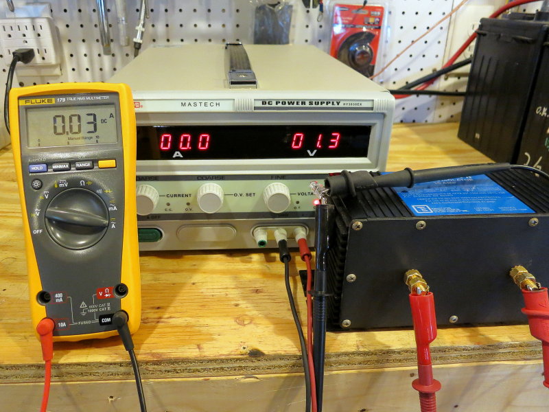
It is a Galvanic Isolator not a Stray Current Isolator
One last very important point on the subject of galvanic isolators. The name of these devices tells a story and makes a very important point GALVANIC ISOLATOR. Galvanic isolators are only capable of blocking voltages created by connecting dissimilar metals together in an electrolyte (the Ocean).
GI’s DO NOT BLOCK STRAY CURRENT FROM LEAKS THAT EXCEED 1.2V
Galvanic voltages do not really exceed 1.2V and this is why a galvanic isolator works at blocking galvanically created current flow. Stray currents absolutely exceed 1.2V and this is why, in the very beginning, I mentioned my preference for an isolation transformer if the ultimate in dockside isolation is what you’re after. This is why you would never see my own personal vessel, plugged into a marina, relying solely on a GI. A GI is certainly cheap insurance against galvanic corrosion, and bare minimum device if plugging into shore power, but a GI does little to protect against stray current corrosion.
If you desire true isolation then an isolation transformer would be necessary. Alternatively you can just unplug from shore power, like mooring sailed boats.
Like What You Saw Or Read?
Would you like to see more articles like this? Is so feel free to donate, support the site and keep it growing.
Please DO NOT feel obligated at all. If you like it and want to make a small donation than that’s all I ask.
Your donations help keep the content coming and also help keep it free.
Click the DONATE button below if you would like to make a donation via PayPal.