Voltage Transients in Marine Electrical Systems
I had been meaning to put this together for a while and assembled a system for a training class I was doing. Once that was assembled I realized I could simply add a starter motor, an oscilloscope and a Fluke 289 & Fluke 376 and then would would was able to create a video on voltage transients.
In the video below I’m walking through the very typical, though not necessarily ideal, marine battery system which utilizes the venerable 1, BOTH, 2, OFF battery switch. The typical 1, BOTH, 2, OFF switch is configured for both bank charge selection and bank use selection.
With the switch configuration in the video, identical to most factory systems, the battery bank selected, via the switch, serves as both a house bank and starting bank as well. It also selects which bank is getting charged either bank 1, bank 2 or BOTH.
Photo:
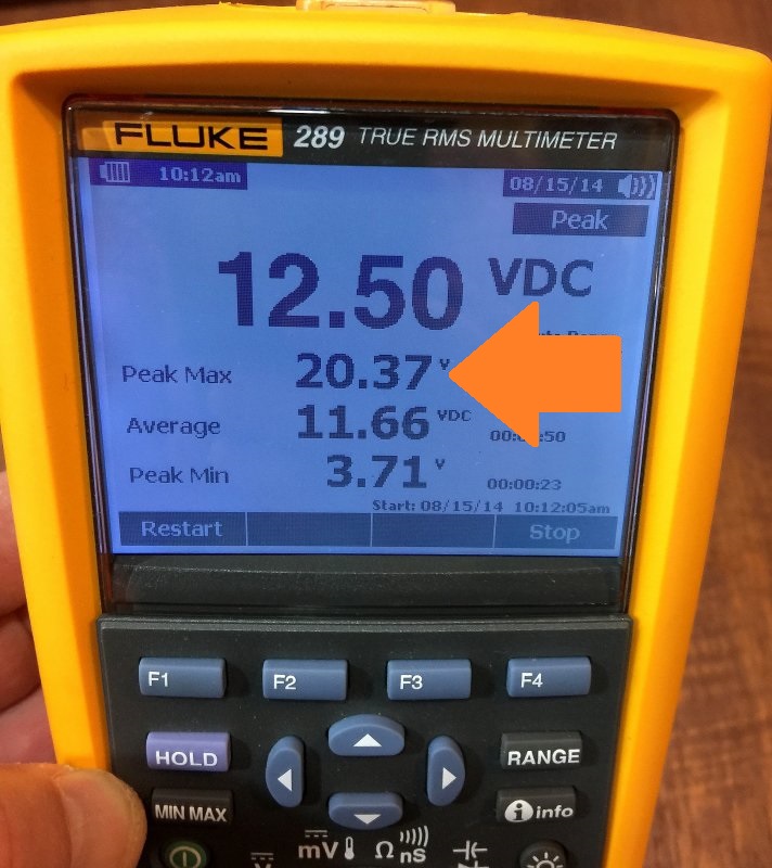
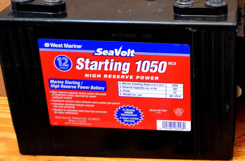
This image was taken on a customers boat who was complaining of poor windlass performance. The windlass on this vessel is connected to the common post of 1/2/BOTH switch, like it is on many boats. This owner had been told it was best to use his windlass on his “starting battery”. With a 1/2/BOTH switch you really just have two battery banks not a dedicated starting battery. His Group 27 West Marine starting battery was passing a Midtronics CCA/MCA test but it failed to drive his windlass motor, in the manner he expected, for the duration needed to raise the anchor.
This image, showing the voltage transient created by a windlass, is a prime example of why merely creating a dedicated & isolated starting bank will not remove all potential for voltage transients in a marine DC system.
There are basically two scenarios related to battery switching which folks often discuss;
- DC Brown-Outs
- Voltage Transients
Electrical brown-outs can happen when the bank is under sized, unhealthy or over discharged for the loads applied to it. It can also occur on an incorrectly wired system due to voltage drop in the system wiring. If the DC electronics are on the same bank being used for high loads then the electronics may drop out when the starter, windlass or other high draw item is called upon. Brown outs, while annoying, rarely cause any damage to equipment. On a cruising boat with a decent sized house bank, that is properly wired, electronics drop outs should not occur even when starting the motor.
Voltage transients are another story and can be damaging to some electronics. I say some because any good electronic design, from the last 30 years, should already have transient voltage suppression capabilities on the input path.
It’s Not just Starting Motors:
The vast majority of windlass installations, on sub 45′ vessels, are wired to the house bank and there is nothing wrong with this. The house bank is almost always considerably larger and in almost every situation can drive the windlass motor far better than a typical starting battery will.
Starting batteries are rated for 30 seconds use with a terminal cut off voltage, at 30 seconds, of just 7.2V.. Raising 200-300′ of chain is not a 30 second operation. Most automotive engines start with a cranking duration of about three-quarters of a second. Cranking duration is; starter loaded to unloaded. A starter battery, intended for 3/4 of a second of cranking of auto motors, is really a poor choice for windlass use and leads to anemic performance.
As can be seen in this image the voltage transient created by the windlass was over 20V. While I was not there to test for voltage transients what I did find was that the owners starting battery was totally inadequate for driving his windlass and his windlass wire was grossly undersized leading to a low voltage at the windlass end of just 4.40V.
“Ah yes, you do have poor windlass performance.”
The “fix” on this boat was easy, I then switched over to the house bank, which consisted of four GC2 6V batteries wired series then parallel, and the peak low voltage at the windlass end jumped to 8.92V. Still, the owner had bad wiring but, his windlass performed considerably better on the larger bank rather than the smaller one.
The video below will walk through this and you’ll be able to see this, with instrumentation connected.
Voltage Transients in A Marine Battery System
.
“You Must Have a Dedicated Starting Battery”…..?
This tome, gets repeated over and over on docks in magazines and on the web. While there is a bit of good in it this statement there’s also some myth. While a dedicated starting battery is never a bad idea it is also not a 100% solution to eliminating transients in a marine system. So, what is a dedicated start battery?
Dedicated Starting Battery: A battery used and wired as such that its only purpose is for starting the motor and powering the engines electronics/gauges. It may also be wired to serve as the “emergency bank”, if needed, in an emergency situation.
A dedicated starting battery, in normal everyday use, isolates starting loads from house loads. Unfortunately starter motors are just one example of devices that can create a voltage transient. In this regard where you connect your DC panel loads matters, and can serve to minimize the potential for transients.
Potential Damaging Sources – Other Than Starter Motor:
- Windlass
- Bow thrusters
- Electric Winches
- Electric Windshield Wipers (power boats mostly)
- Engine Driven Refrigeration Clutch
- DC Motors (these transients can occur on the negative side too)
- DC Refrigeration
- Water Makers
- A Load Dump of an Alternator
- Inverters
- Water Makers
- Electric heads
- Water & Washdown Pumps
- SSB Radio
- Bilge Blower
- Battery Charger
- Battery Switch
- Relays, Solenoids & Combiners
- 12V Appliances – Blenders etc.
- Electric Oil Pumps
- Bilge Pumps
- Etc. etc..
By connecting the loads or equipment closer to the engine or tapping into a negative near the engine or positive lead near the engine you increase the potential for equipment seeing a transient from the starter motor. Lots of DIY’s and pro’s too, don’t fully grasp this concept…
Despite all the above potential sources of transients, in well wired boats I rarely measure transients above 14V – 15V.
With poorly wired systems we measure spikes exceeding 30V !
It’s important to recognize that the act of using adedicated starting battery does not remove your house bank of the risk of voltage transients. This is because starter motors are not the only potential source of transients. Many sources of transients actually need to reside on our house banks.
Spending the money on a dedicated starting battery, despite all the marketing efforts by battery switch makers etc, will simply not remove all the potential for transients from your marine house bank.
Keep your DC load positive & negative take off points as close to the battery bank as possible, and only use one take off point for DC panel loads, and you can minimize the potential for damaging transients.
Start & House Battery “Isolation” Switches
.

While this vessel does have a dedicated starting battery, which is completely isolated from the HOUSE system, the vessel also has numerous other items than can potentially create voltage transients. While this owner believed he had eliminated voltage transients the HOUSE system still has:
- Windlass
- Electric Halyard Winch
- Engine Driven Refrigeration Clutch
- Multiple DC Motors (these transients can occur on the negative side too)
- Water Maker
- Potential for Load Dumping the Alternator (passes through batt switch)
- Inverter
- Electric Head
- Washdown Pumps
- Bilge Blower
- Battery Charger
- Battery Switch
- Relays & Solenoids
- Bilge Pumps
As can be seen, the act of isolating the starting circuit only really removes just one of the many potential sources of voltage transients.
If a boat yard or service tech claims; “You must have a dedicated starting battery” please research their recommendation. Also research this well beyond this article. I am but one source! Also, be sure the tech is using qualified test equipment when they make this recommendation, to ensure they are not just shooting from the hip, at the expense of your wallet. Ask them what the measured peak transient voltage, at the DC panel, was? Ask them which test equipment they used, that is fast enough, to capture these transients? If you do this you’ll likely see them start to squirm a bit.
Unfortunately I see far too many boat owners lulled into a sense of security over “must haves” that may not make financial sense nor actually solve the issues they claim to be solving.
Please understand that I am not at all against a dedicated starting bank, I actually prefer them, when it makes sense. Unfortunately not all cases warrant this level of re-wiring or cutting of new holes for switches that justify the modification.
Let’s Not Entirely Blame The Switch
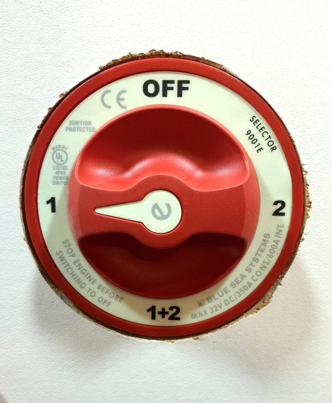
If I had a dime for every time I’ve heard that a 1/2/BOTH switch is the cause of damaging voltage transients, I might be retired. The 1/2/BOTH does not create voltage transients. The reality is that haphazard/poor wiring practices and poorly designed equipment, that can be damaged by such transients, are the other major parts of the problem.
Perhaps the biggest risk of blaming the 1/2/BOTH switch, as it relates to transients, is that once folks remove it, and crate a dedicated START bank, they assume they are out of the woods, and this thinking is very often misguided.
Proper Wiring of Your System Minimizes Risk

Batteries act as very good transient filters clamping the voltage down pretty quickly. It takes huge amounts of amperage in charge current to increase bank voltage a few tenths of a volt when charging large house banks. Transients can be extremely fast and can increase voltage in the system wiring quickly but as we get closer to the bank the transient range is greatly reduced. This is why one central take off point, as close to the battery bank as is possible, for your DC system, is best.
Unfortunately if your wiring for sensitive electronic items, such as marine electronics, is not as close to the batteries as is possible, or the supply feed for them is not close, you widen the risk of transient damage.
In this image the positive and negative take off points for the DC panel are as close to the battery as is possible. Also of importance is how close your battery switch is to the actual battery bank. Builders often grossly miss this mark and spend huge amounts of wasted money on massive starting cables when it is not necessary or ABYC complaint.
IMPORTANT: This, and the next few images, are illustrative only. For clarity & simplicity the images lack proper over-current protection etc..
Common Mistake #1
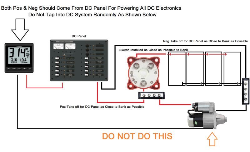
This image is one of the most common mistakes I see, by both pro’s and DIY’s, when it comes to wiring sensitive electronics. The negative wire for the electronics circuit is grabbing its take off point from the engine room. This could also be any old random spot in the DC system and it can be near equally as bad. Grabbing any old DC negative connection point, because it is convenient, is a very poor practice, on numerous fronts, and it can lead to potentially damaging transients.
It seems far too many folks believe that a negative is a negative, and it all leads back to the battery, so it does not matter where you tap in, but it can. As can be seen from the video above it matters greatly where you tap into the system wiring & it matters for both for the negative and positive sides of the circuit.
Common Mistake #2
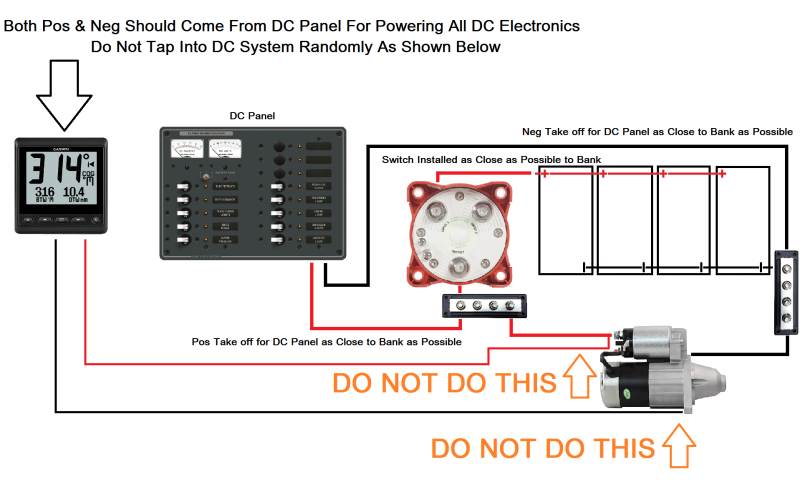
Yes I know some of you are laughing and thinking this would never happen but, sadly it’s more the norm than the exception. In this image the sensitive DC electronics have been tapped into the starter post and the engine room negative.
If you want to increase your risk of transients wire you system like this. If you want to decrease your risk of transients wire as shown in the first of these diagrams.
What Else Can I Do?
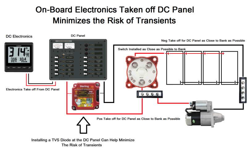
Seeing as it is not just the starter motor that can cause transients, one trick you can do is to insert what is called a TVS diode across the DC Electronics circuit or the DC Panel power feed. Unless you are an EE and know how to properly size a TVS Diode, the easiest option for this is either the Balmar APM (Alternator Protection Module) or the Sterling Power APD (Alternator Protection Device). These are both very robustly built voltage suppression devices (more than just a TVS diode) They are built to handle alternator load dumps, arguably the most difficult transients to suppress. This means they can easily protect voltage transients from any other DC device..
Buy A Voltage Suppressor – Bay Marine Supply
A TVS diode is otherwise known as a transient voltage suppressor diode. Most DC electronics today already have TVS diodes on the input path, just as they do in the automotive world but, not all do. As added insurance, one can also be placed across the DC Panel or the DC electronics feed in order to clamp transients at the panel or circuit level.
A TVS diode is a diode designed to protect electronic circuits against voltage transients and electrically fast over-voltage threats, also known as EFT’s. In certain situations they can also serve to protect against electro-static discharges. TVSD’s are considered avalanche type devices and electronic design engineers choose them to fit the design application based on multiple parameters, hence why adding a TVS Diode id not a DIY level job..
An example of a pre-made & pre-packaged TVS diode (and other filtering electronics), that is actually available in the marine market, would be Sterling Powers APD or “Alternator Protection Device” (as shown in the diagram). The APD is designed to mount across an alternators B+ & B- output terminals to protect the alternator diodes & DC system from a load dump or disconnect from the battery bank while the alternator is operational. That said, the Sterling APD is not just limited to clamping transients from an alternator load dump it can also be placed across a DC electronics circuit or across the DC Panels B+ & B- feeders for added insurance, especially in systems where the wiring is suspect or an unknown quality.
If your system wiring is a mess, and you’re interested in a Sterling Power Alternator Protection Device (transient suppressor), they sell for about $85.00
Battery Switching Builder Blunders
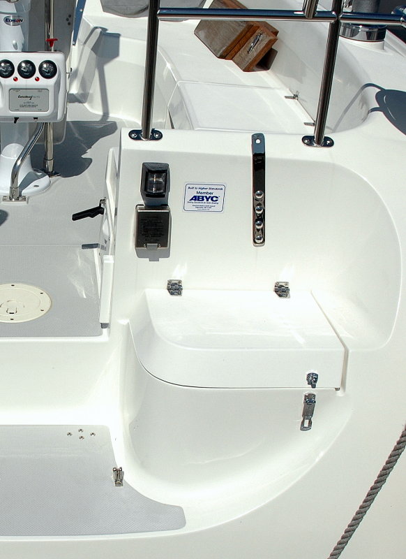
Before we examine this part of topic I want to point out what the accepted marine safety standards call for in regards to battery switch location.
ABYC E-11 July 2015
“Battery Switches:
11.6.1.2.2 A battery switch shall be mounted in a readily accessible location as close as practicable to the battery.“
We purchased this vessel brand new in 2005 as a 2005 model year. It proudly wore the ABYC sticker designating it a boat that was built to the ABYC standards.
Battery Switch Actual Location

While this type of switching set up seems convenient and looks appealing at boat shows, don’t be fooled. This is one of the worst locations for a battery switch I know of.
#1 The massive 1/0 or 2/0 cables place tremendous strain on the plastic DC panel when it is opened for servicing.
#2 It requires far more expensive battery cable than is necessary.
#3 It increases the length of wire in the starting circuit leading to voltage drop and poorer starter motor performance.
#4 It creates vastly more locations for wire chafe & vibration to short-out the battery cables, often in areas that are physically inaccessible.
#5 It places your DC panel smack-dab in the middle of the circuit, & far far away from the battery, thus increasing the risk of transients.
#6 It is not in compliance with the bare minimum ABYC safety standards for battery switch location.
Battery Switch Wiring Path

As can be seen, by the layout, the battery banks, both start & house, were located under the PORT settee. The starter motor is a mere 3.5 feet from the battery banks yet the builder chose to put the switch on the STARBOARD side of the vessel and create a 20 +/- foot circuit, and I’ve not even included the negative side of the circuit in this calculation.
The battery switch could have been mounted flush with the settee/battery box and still meet ABYC standards. Doing so would cost the builder less in wiring, not require the 1/0 battery cables to be run long distances though the bilge, result in better starting performance and create less risk of voltage transients to items powered by the DC panel..
I don’t know how the builder justifies calling the vessel “Built to ABYC Standards” with battery switch wiring that is so flagrantly outside the standards requirements that it’s laughable.
Keep your battery switches as close to the bank as possible, in a location that will physically allow good access. If you want remote battery switching Blue Sea Systems offers the excellent ML-RBS series of remote battery switches.
Do your best to wire your DC loads well and transients should not be a concern. Wire them in a hap-hazard manner and transients can be a concern.
Good luck & happy boating!
Let’s Keep This Site Running!
Like what you saw or read? Would you like to see more articles like this? Is so feel free to donate, support the site and keep it growing. I am trying my hardest to keep this information FREE. If you liked it, learned from it or I saved you some money feel free to make a small donation, that’s all I ask.

