Incorrectly Wired Service Disconnect Switch
 This article is part of an on-going series on marine alternators. Our other articles can be found in the link below:
MarineHowTo.com Category – Alternators (LINK)
Terms used in this article:
Alternator B+ = Positive Alternator Output Wire
Alternator B- = Negative Alternator Output Wire
Regulator B+ = Red regulator power wire for the MC-614 (terminal #2)
Regulator B- = Black wire in regulator harness used for negative power and voltage sensing (terminal #1)
Load = Battery Bank
Full Field = Alternator regulator driving the maximum field
ASD = Alternator Service Disconnect Switch
AFD = The Alternator Field Disconnect feature found on certain battery switches
What is the purpose of a Service Disconnect Switch?
The service disconnect switch is designed to disconnect the alternator B+ wire from the battery so a service technician cannot short a wrench to the B+ stud while working on the engine. It is there to help service technicians isolate the alternator from the battery bank, that’s it.
Why would my alternator be directly wired to the battery bank?
When wiring any high performance marine alternator & regulator the optimal charging performance will be realized when wired in the following manner:
- The alternator B+ & B- are directly wired to the house bank or the bank that gets routinely discharged the most
- The alternator regulators voltage sensing circuit is directly wired to the same bank the alternator is wired to
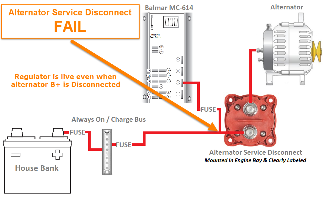
If your paying attention to the wiring laid out above, you’ll quickly realize that even with the main battery switches set to OFF the alternator regulators B+ / power wire still has live power from the house bank. This can be dangerous to a service technician who may be working on your engine and not know or realize the alternator is direct wired to the house bank. Don’t worry, there is an easy way to handle this and it is called an Alternator Service Disconnect Switch or ASD..
Service Disconnect Switch Best Practices
- Should be mounted near engine, in the engine bay (out of sight of your on-board guests)
- Should be clearly labeled as an “ALTERNATOR SERVICE DISCONNECT“
- The power for the regulator must be wired on the alternator side of the service disconnect switch!
- Use the ASD switch only when servicing the engine
Yes, #3 is bold for a very good reason. The most critical aspect of wiring a service disconnect switch, and one that is far too often over-looked, is to ensure the external regulator cannot boot up with the alternators B+ terminal disconnected from the load or battery bank. This means placing the regultors power wire on the alternator side of the ASD switch circuit so that when the ASD is off the regulator is also off.
“Rod, Why on Earth does that matter if the alternator is disconnected, isn’t it disconnected?”
The answer to the above question simple:
Darrell the diesel guy is working on your fuel injection system and he notices that you have an alternator service disconnect switch and OFF it goes.. Darrell knows what an ASD is, because it is CLEARLY LABELED and turns it OFF, while working on the engine, so he does not weld a wrench to the manifold. When Darrell is done servicing the engine, he cleans up, closes the engine bay, but forgets to flip the ASD switch bank to the ON position. D’oh!!
A few hours later you arrive to use the boat. You fire up the engine and think; “wow this baby is really smooth“. A few minutes later you get a whiff of that acrid electrical burning smell……. Ohhhhh…..
If the alternator B+ is physically disconnected from the battery bank, but the regulator is still allowed to boot up, with no “load” on the alternator, the regulator will go to full field and voltage will shoot through the roof. The alternators rectifier diodes are only rated for so much voltage and your expensive alternator can literally have all the smoke escape from it. Not good!
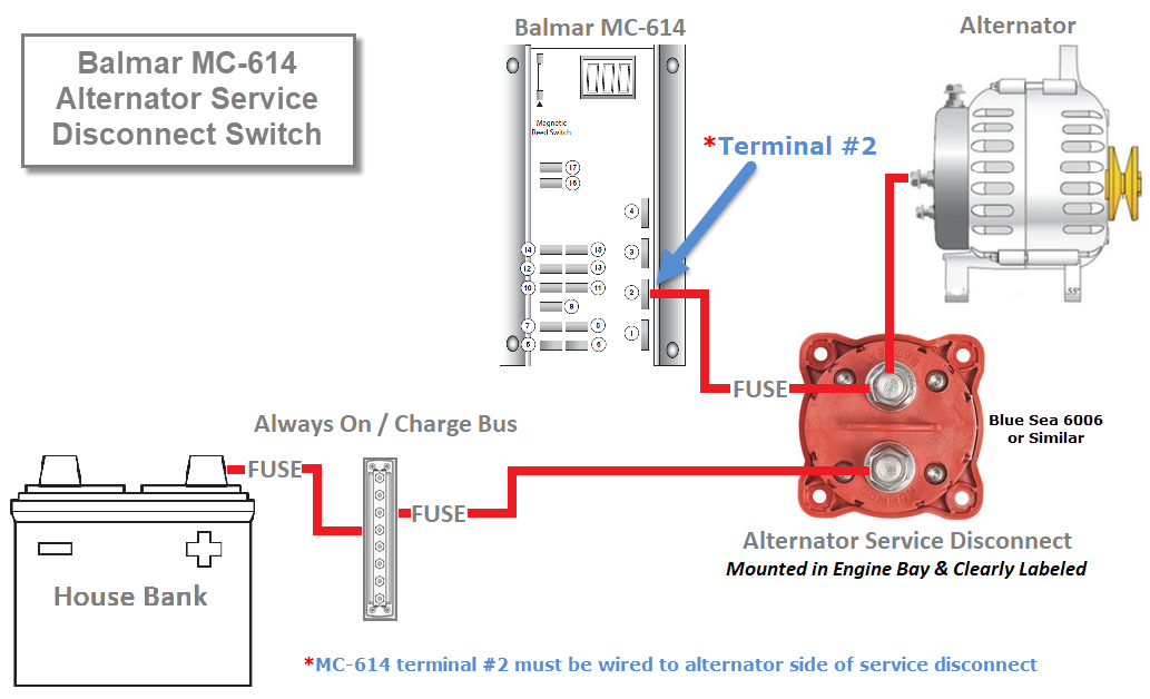
Correctly Wired Service Disconnect Switch – Balmar MC-614
In this image the regulator B+ / Terminal #2 has been moved to the alternator side of the ASD switch. Even if Darrell forgets to turn it back on, the regulator cannot boot up.
An ASD is an excellent way to keep your performance alternator system safe for yourself or service technicians who may be working on the engine. It will also allow you to yield the alternator performance you’ve paid for. For the most part, perhaps 99.9% of the time, this switch left in the ON position. The only time an ASD is used is when servicing the engine. However, in that 0.1% occasion that Darrell forgets to turn it back on, you don’t want to ruin your alternator by having the regulator boot up into a no-load situation.
The Balmar MC-614 external regulator is unique in that it has a separate positive voltage sensing terminal (terminal #9). This means the regulator B+ / Terminal #2 power wire can be installed on the alternator side of the ASD, and not negatively impact charging performance. For more on voltage sensing for optimal chaging performance, please see this article:
Alternators and Voltage Sensing (LINK)
What About the Balmar ARS-5?
With a Balmar ARS-5 regulator, the regulator B+ / Terminal #2 is also your positive voltage sensing circuit and sensing the back of a switch, one that is so close to the alternator, eats away at your quick-charging performance. For a Balmar ARS-5 regulator it will be best to route regulator B+ / Terminal #2 through the AFD circuit (alternator field disconnect), of an AFD equipped battery switch, and then onto battery bank positive terminal or the always on / charge bus. The Blue Sea Systems 9004e is a simple ON/OFF switch with an AFD circuit.
The drawing above also includes an “Always On / Charge Bus”. A busbar like this is a great place to install fusing, such as busbar mounted MRBF fuses. The Always On / Charge Bus is a great place to collect all your charge devices such as alternators, chargers, solar, wind as well as bilge pumps or other devices that always remain ON. A busbar like this helps keep the battery bank free of clutter and limits the need for multiple-lug-stacking.. Fusing is always required at the battery end of an alternator circuit not near the alternator.
Like What You Saw Or Read?
Would you like to see more articles like this? Is so feel free to donate, support the site and keep it growing.
Please DO NOT feel obligated at all. If you like it and want to make a small donation than that’s all I ask.
Your donations help keep the content coming and also help keep it free.
Click the DONATE button below if you would like to make a donation via PayPal.