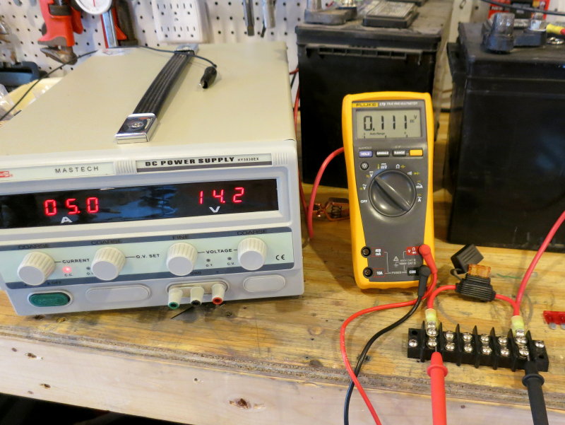
5A Fuse – 5A Load
As boaters looking for optimal charging performance we need to keep in mind that the path between the charge source and battery has voltage drop. This is just a fact of life. For charge sources that do not feature a dedicated voltage sensing correction circuit we need to keep voltage drops to a minimum, for optimal charging performance.
Every switch, fuse, terminal etc., in a circuit, will add a bit more voltage drop, but for safety, these items are necessary. This article focuses on fusing solar, alternators or other charging sources that lack voltage sensing circuits.. It can also be helpful for other voltage sensitive equipment.
When fusing devices such as solar controllers, alternator outputs, wind or battery chargers these devices need to be fused as close to the battery (source) as possible or within a few inches of a change in wire gauge, unless enclosed in a protective conduit. As current increases on a circuit voltage drop increases. Create enough voltage drop, due to resistance, and we now begin to lose charging performance. Unfortunately, for marine use, we tend to only size voltage drop based on the wire lengths, amperage and gauge of wire desired. Most installaters are happy with a 3% voltage drop, based on just the wire, however this can mean a 4% or higher voltage drop when the system is finished and installed due to terminations, switches, breakers or fuses. We simply can’t ignore these additional voltage dropping points in the system especially when voltage drop matters.
A 3% voltage drop in a 14.4V charging system means just 13.97V at the battery end of the circuit.
Remember:
- The wire has a voltage drop
- The terminal to wire connections also has a voltage drop
- The terminal to busbar also has a voltage drop
- The fuse & holder leads also have a voltage drop
- The switch or breaker also have voltage drops
In voltage critical circuits aiming for 3% voltage drop, based on the wire only, will not lead to the charging performance you desire. So how do fuses play a role?
#1 Fuses should be sized to not exceed a continuous current of more than 80% of the fuse or breakers rating. Doing so will lead to short fuse or breaker life and the potential for nuisance trips. It also leads to excessive voltage drop across the fuse.
#2 When sizing for charging systems it is often best to use a fuse that more closely approaches the maximum ampacity of the wire. Doing so will still protect the wire but will also result in less voltage drop across the fuse. In other words it will be helpful, from a voltage drop perspective, to use the largest size fuse the wire can handle. Doing so will minimize any added voltage drop across the fuse.
“My solar panel can only put out 4.5A so I used a 5A fuse.“.
Unfortunately this is a flawed mind set to be in. In this scenario a better approach would be;
“My 10GA 105C rated wire has a max ampacity of 60A, outside of an engine compartment, so I ideally should use a 30A – 60A fuse.”
This photo shows a 5A fuse at a 5A load. The fuse is adding an additional 0.11V of voltage drop to the losses already there in the wiring and terminations. If we go back to our example of sizing for a 3% wire loss, we are now at just 13.87V at the battery terminals, with a target of 14.4V, and we’ve not yet accounted for any other terminations.
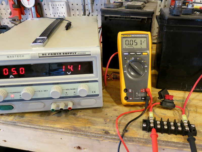
10A Fuse – 5A Load
Here is the same exact scenario, except this time we’ve used a 10A fuse with the same 5A load. It is dropping just 0.051V vs. 0.111V. We’ve essentially cut our voltage drop across the fuse in half!
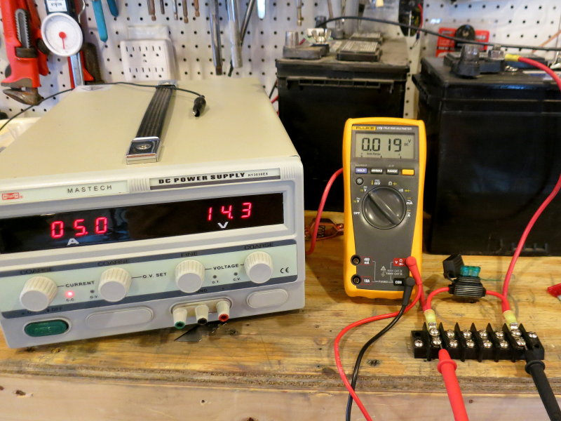
30A Fuse – 5A Load
This is the same set up now with a 30A fuse and we’re now down to a 0.019V drop…. The smallest wire, in this case, is the short section of the 12GA fuse holder. It has a max ampacity of 45A so even at 30A the wire is extremely well protected and safe from a short-circuit event while at the same time minimizing voltage drop.
The key take away here is that using the largest fuse, that is well within the safe ampacity range for the wire, results in the least voltage drop in your system wiring.
Max Ampacity Chart – Non-Bundled Wire
Here’s the ABYC E-11 wire sizing chart for maximum allowable wire current carrying ability or max ampacity. This is the chart to use when sizing for fusing or over current protection, when the wires are not bundled together.
Find your wires AWG gauge in the left column then move over and find the jacket temp rating. Most “Marine UL” wire has a jacket temp rating of 105C, but do check because this is not always an absolute.
When sizing for voltage sensitive sources, or when ever voltage drops can make a difference, such as in charging systems, it is a good idea to size to the max ampacity of the wire, or close to it, rather than what your charge source can supply in current to base fuse sizing on.


Testing for Voltage Drop
“RC how do I measure the voltage drop in my existing system to find problem areas?”
When measuring voltage drop the most accurate method is to begin by measuring both the positive side and the negative side of the DC circuit independently. This helps to isolate where the biggest volt drop issue or problem may lie.
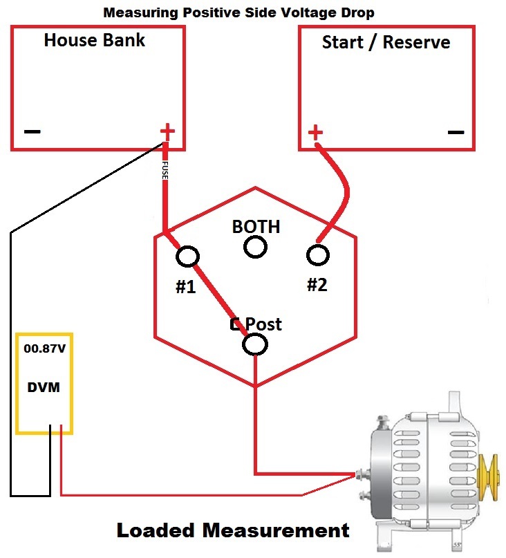
To test for voltage drop simply connect one of your digital volt meters (DVM) test leads to the battery + terminal and then the other lead to the terminal of the device being measured. As shown here, the neg test lead is on Battery + and the positive test lead is on Alternator B+
Remember, it takes current in the circuit to create a voltage drop. With zero load you should read 00.00V, as shown here, because it takes current passing through the wire to create the voltage drop. No current, as pictured, means no voltage drop.
Fire Up The Charge Source
In this image the alternator has been turned on and is supplying the maximum current it can. You can trick any charge source into supplying its full output by placing a large load on the battery that either equals or slightly exceeds the charge sources maximum capability. An inverter and variable AC load is a perfect device for this.
In this test we had an alternator supplying 78 – 80A of charge current with a 0.87V drop just on the positive side of the circuit. This is an excessive amount of voltage drop, especially on just one side of the circuit. The negative side of the circuit was losing 0.65V, for a grand total of -1.52V of drop.
This example was taken directly off a customers boat. He’d undersized the wire and also made the crimped terminations with pliers. His fuse for the 90A alternator was 100A.
His charging system was essentially dropping nearly 11%, and his charging performance was horrendous. Ideally a charging system should loose well under 2% if you want any sort of performance out of it.
The test illustrated here can be used on the negative side just as easily as the positive side. You can then further test from:
Alternator B+ to C Terminal of Battery Switch = Wire & Terminal Drop Between Alt B+ & Battery Switch C Post
Across Switch C Terminal and Switch #1 Terminal = Voltage Drop Across Battery Switch
Switch #1 Terminal to Switch Side of Fuse Holder = Drop In Wire/Terminals Between Switch #1 and Fuse holder
Switch Side of Fuse to Battery Side of Fuse = Fuse Voltage Drop
Battery Side of Fuse Holder to Battery + Terminal = Wire & Terminal Drop Between Battery + and Fuse Holder
What About Termination Resistance?
As a marine electrician I have to work in the real world of actual measurements based on the as installed system.. Frustrating as it may be the marine industry, most books and even the ABYC have let us down on properly sizing our systems for voltage drop. The key word here is “system“. As related to voltage drop the “system design” should really include, the additive drops across all switches, terminations, fuses, isolators etc. etc. and were we are “sensing” the voltage.
Here is a prime example:
Marine tech John Doe sized for a 3% wire voltage drop for a customers new “high output” alternator. The 3% figure he used was based solely on the wires voltage drop. A 3% drop at face value, is already a -0.44V drop at 14.7V and will lead to slower charging. This is far from ideal for an expensive performance charging system where the owner expects short run times and maximum energy storage. To further complicate matters the tech apparently did not understand the correct way to install the performance voltage regulator and he was sensing voltage at the alternator itself. For more on this subject see:
Alternators & Voltage Sensing – Why It Matters
Boaters, including far too many professional techs, often forget the fact that the voltage drop calculation is based only on the wire drop. They ignore all the other things that add voltage drop in the “installed system“. For most circuits a 3% wire drop can be suitable, or is marginally acceptable, but it’s not adequate to size like this for a performance charging system. It’s not just the off-shore sailboat racer who needs to cram the maximum Ah’s they can, back into the bank, in the shortest time frame possible. Let’s face it, no one likes to listen to the engine or generator run any longer than it has to. In the end this owner spent big-bucks and the system did not meet his design expectations, for offshore racing, or what the tech led him to believe it should do.
That is when I was called in…
“Real world“, in this case, meant that when the wires were finally run, the length, according to the owner, “was a tad longer” than the tech has guessed it would be. The wire passed through multiple lugs/terminals, a fuse, switch, busbar etc. and each and every connection adds more voltage drop to the wire loss. The tech also used sub-par crimp tooling for each termination.
The way this was wired meant there were 16 connection points on the negative side and approx 6 on the positive side including a fuse and an alternator service isolation switch.
“RC, how do you figure the drop of all these connection points?”
Over years of field examples and tests. I tend to use a sizing factor of *0.00025Ω per connection point, as the resistance.. *This number assumes the connections are clean, tight and not made with a Dollar-Store crimp tool. You can see better performance than this with good tooling but I find 0.00025Ω pretty safe for sizing purposes.
For example:
Each Lug/Terminal = wire to lug as #1 & lug to XX point as #2.
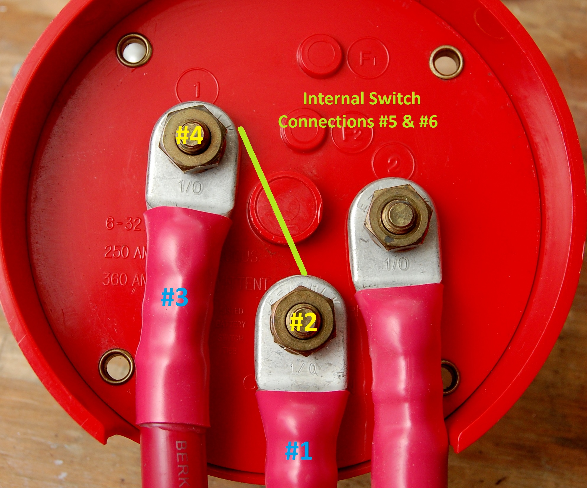
This means two connection points per lug or terminal. This 0.00025Ω seems to bear out quite often but more importantly it means more accurate up-front voltage drop sizing. It would be quite stellar to see a 1.37% voltage drop (-0.2V @ 14.6V) but as installed that rarely happens especially when you size for 3% and fail to take all the terminations, switches etc. into account. In the image to the left we can see that the simple path from the “C” post to the #1 Post of a typical battery switch results in six connection points alone.
Let’s run the numbers on just the connection points at 80A:
22 Connection Points at 0.00025Ω = 0.0055Ω
80A X 0.0055 = -0.44V
This -0.44V drop is on-top-of the 3% wire voltage drop of -0.44V for a grand total of -0.88V. At absorption voltage, & 80A of alt output, his batteries were only seeing 13.82V instead of 14.7V.. Ouch! Voltage is the “pressure” that allows the current to flow into the battery. Lower voltage means less current can move from the charge source into the battery and results in slower charging.
If you don’t want to do all this math, you can just size for 1% to 1.75%, based on wire, and you’ll end up in a much better place for your charging system. When sizing for voltage drop, in a voltage critical system, use every tool you can to arrive at the lowest acceptable voltage drop you can reasonably estimate and do the math before you purchase the wire..
Good luck and happy boating!!
Like What You Saw Or Read?
Would you like to see more articles like this? Is so feel free to donate, support the site and keep it growing.
Please DO NOT feel obligated at all. If you like it and want to make a small donation than that’s all I ask.
Your donations help keep the content coming and also help keep it free.
Click the DONATE button below if you would like to make a donation via PayPal.