Battery Monitor Diagram
This article features the older Victron BMV-602. The 602 has been replaced by the BMV-7oo series. Everything in this article is still relevant to the current series of BMV monitors.
Purchasing recommended products from our affiliate partners.Helps keep content coming! We give you two excellent purchasing options below.
Buy MHT Recommended Battery Monitors- Current Connected
Buy MHT Recommended Battery Monitors – Bay Marine
Installing A Battery Monitor:
The battery monitor is a very useful tool for a boat-owner who has to survive on battery power. When properly installed & properly calibrated they can extend the life of a battery bank.
Allow me to re-emphasize:
WHEN PROPERLY INSTALLED – About 90% of Ah Counters we come across are NOT properly installed & wired.
WHEN PROPERLY CALIBRATED – About 98% of Ah counters I come across are NOT properly calibrated/programmed.
When not properly installed, and kept well calibrated, Ah counters can be horribly inaccurate…
Rule #1 for most tradittional Ah counters:
Disable the “auto-sync” feature and use manual “known-full” re-sets.
What is known-full?
- Voltage at 14.4V+ = ✓
- Net accepted current less than 1.5% of Ah capacity = ✓
- Okay to reset to 100%
NOTE: Battery voltage should be at absorption level not a float voltage when performing a manual known-full reset. If you have been at a dock at float voltage for multiple days then it is safe to assume you are full and a manual reset is fine. When out cruising use absorption voltage.
FACT: From the day you install your bank the physical Ah capacity is ever changing. The biggest problem with traditional Ah or Coulomb counters is keeping them accurate with the batteries physical condition. As batteries age their capacity changes, it is an ever moving target, so the 100Ah battery you bought three years ago may now only be a 75Ah battery.
If your battery monitor is still programmed for a 100 Ah capacity, and you are drawing 50% of the assumed Ah capacity out of it, based on this 100Ah rating, you are really now drawing the bank to just 33% SOC. Oops….
Inaccurate assumptions can lead to erroneous data:
You had 100Ah programmed into the Ah counter. Your battery, due to age and use, is now 75Ah’s. You now draw 50% of 100Ah’s out of the battery, except the battery is only really 75Ah’s and you wind up at;
100Ah Assumption = 50Ah Removed:
75Ah – 50Ah = 25Ah = 33.3% Actual SOC
Actually if you threw Peukert’s exponent into the mix you may actually be lower or higher depending upon the actual load at which it was drawn. Holy cow this is confusing….!
This is just one example where an Ah or Coulomb counter can become inaccurate in relation to the actual battery bank. These devices are not plug & play and are only as smart as you make them. Please be aware of this.
Coulomb or Ah counters count Ah’s very, very accurately. However, they have no clue about your banks physical Ah capacity or its actual state of health. It is up to you, the owner, to tell it the bank capacity and program for this as accurately as you possibly can. T
With traditional Ah counters, a trick many of us in the industry use is to start with a slightly lower programmed Ah capacity than the bank is rated for. So for the 100Ah battery I might initially program it at 95Ah’s so the owner is never actually drawing to 50% SOC that first year (self protective feature). The next year I might remove another 3% – 8% off the capacity etc. etc.. These are just rough guesstimates, for most, unless you have the capability to run a true capacity test. On many banks it may tend to correlate marginally, but don’t expect guestimates to be perfect.
I also count on the fact the battery is being drawn at average discharge currents that are below the rated 20 hour load. This can lead to slightly more bank capacity, but again this gets confusing for the average boater to understand, especially when we bring our good friend Mr. Peukert into the equation.
The only way to accurately know your battery capacity is to perform a constant current RC test or a physical 20 hour discharge capacity test. This is complicated, time consuming, and very few boaters are willing to do this. To be honest I don’t know of a single boater who actually has conducted an accurate 20 hour load test.
Ah / Coulomb counters rely on the actual 20 hour capacity figures being accurate, to actually remain accurate for SOC, over time. Without an accurate 20 hour capacity figure there is no real SOC accuracy in the Ah counter, only a close-enough or hip-shoot range. This may not be half-bad but is a a decent margin away from yielding an accurate SOC. Just be aware of this when you are assuming your Ah counter is accurate, in relation to your bank.
Unfortunately the scenario laid out above, for a traditional Coulomb/Ah counter, is just one of the many ways these devices can become tripped up and lead to inaccurate SOC readings. There are other gotcha scenarios that can rear their ugly head too. Please take the time to read the sister article to this one:
Making Your Battery Monitor More Accurate
Gotcha’s may include shunt wiring mistakes, battery temperature, charge efficiency calculations, PSOC use, varying charge rates, Peukert, false re-syncs caused by solar or wind, changes in physical Ah capacity, changes in charge efficiency as the battery ages, incorrect programming etc. etc..
Despite all the way Ah counters can get tripped-up I suspect the big reason they usually lead to longer bank life is simply because they make owners more aware of their bank. More awareness of your bank and charge source performance is important. More awareness can play a larger role than we may otherwise assume.
For years I’ve been trouble shooting and helping owners try to use these devices in a smarter and more accurate manner. Unfortunately it often feels as though I beat the drum inside a sound proof room and no one can hear it. When owners understand how an Ah counter works, they can be very useful. Most all of my customers have had longer battery life as a result of an Ah counter.
With new battery technologies costing three to ten times what wet cell technology does and many boaters moving to newer technologies such as GEL, AGM, TPPL AGM and LiFePO4 Li-Ion batteries, accurate or as accurate as possible monitoring, of an expensive bank, is almost a prerequisite.
People often ask me questions about how to install a battery monitor so I took some time and tried to make it simple. They are actually easy to install but there are a couple of gotcha traps that you may find your self falling victim to.
There are a fair number of Traditional Ah counting battery monitors on the market;
- Blue Sea Systems 1830
- Xantrex LinkLite & LinkPro
- BEP
- e-Xpert
- Victron
- NASA
- Philippi
- BM Pro
- Cristec
- Bogart Engineering
- Mastervolt
- etc. etc..
The Victron units, featured in this article, are some of the easiest to install and also some of the least expensive.
.
Three Generations
From left to right I have three generations of battery monitor represented. The original Link 10 was manufactured by Cruising Equipment Company and they really started a good thing. Despite many of the “LINK” products tending to be a little buggy they were generally well regarded and loved by boaters.
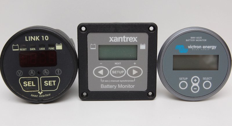
Somewhere along the way Cruising Equipment became Heart Interface and then Xantrex bought Heart Interface. Xantrex then found TBS Electronics in the Netherlands and began importing and re-branding the TBS made monitor as the Xantrex XBM (pictured in the middle). The XBM was the identical battery monitor to the Victron 501 and was a very, very reliable device. It also offered a computer interface option, something new to battery monitors at the time.
Eventually Xantrex made the switch to all TBS built battery monitors such as the current Link-Lite and Link-Pro. They have proven to be solid though very expensive units.
About the time Xantrex signed on to re-label the TBS monitors Victron found a new manufacturer to build their units, though I don’t know who it is. The Victron BMV-602S is pictured on the right and bears little resemblance to the TBS built monitors.
Victron BMV-602S Shunt
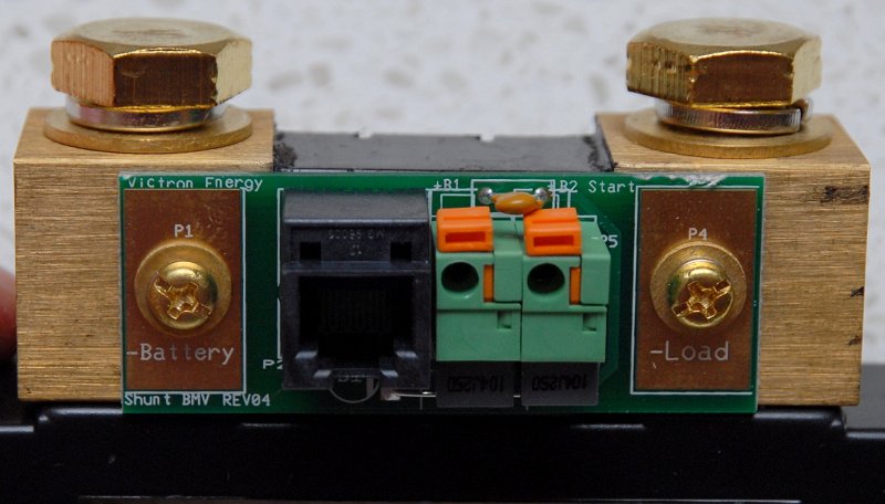
The Victron shunt is quite unique because they have added a printed circuit board to it so that wiring is much easier. Shunts are not really directional devices but because Victron added the printed circuit board / UTP cable connector it does make it directional.
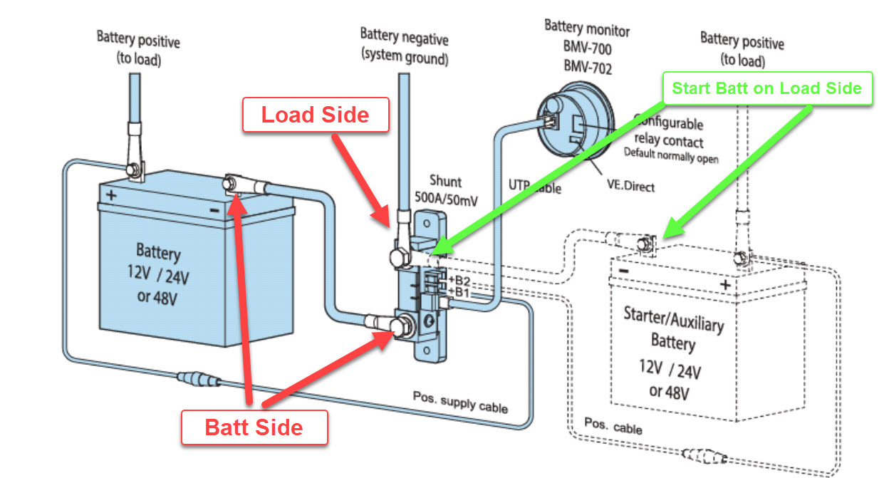
The shunt is labeled -LOAD and -BATTERY. DO NOT wire this backwards or it will not work properly. The side labeled -BATTERY must be connected to the battery neg post and the side marked -LOAD must see the system negative loads.
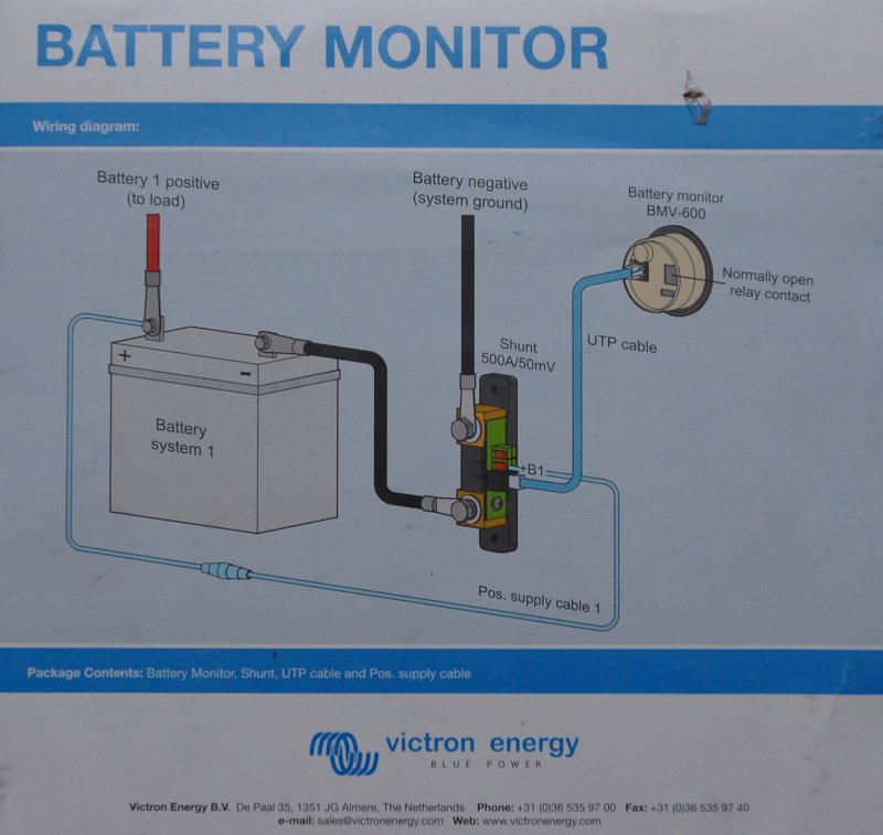
This monitor is VERY easy to install. It has just two wires, a UTP cable & a power cable. The UTP cable is 10 meters or roughly 33 feet long, allowing plenty of display mounting options. The UTP cable is the only wire that needs to be run the monitor display. It’s literally “plug & play”. The UTP cable is very similar to a phone cable, only slightly more robust. The red power supply wire simply connects to the positive battery post and the +B1 terminal of the Shunt.
This shunt has two power supply inputs, +B1 & +B2 for two banks, as it can monitor the voltage of a second start/reserve bank.
Wiring Layout
 Where Does The Start Battery Connect
This is simple but is often messed up . The start battery goes on the load side of the shunt.
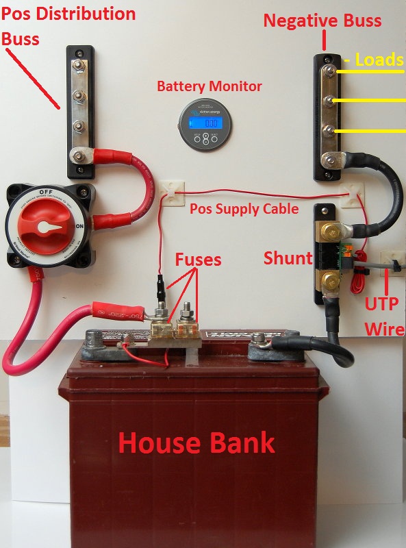
I tried to wire this up on the bench to replicate what one might see on-board a boat. This is explanation is just far to difficult to illustrate on a boat. I actually photographed this quite a while ago, on a boat, and decided not to use any of the photos.
Obviously a house bank would be comprised of multiple batteries but the point is the same. A single battery was used for illustrative purposes only. If your boat is not wired with a positive or negative distribution buss it can help organize the wiring tremendously.
I have also shown a Blue Seas double MRBF (marine rated battery fuse) block on the battery post. I use one for the house bank and one fuse for the alternator which I generally always wire direct to the house bank.
Loads OK / Loads Not OK
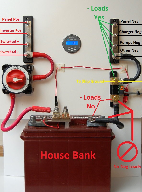
OK here’s the gotcha we talked about. Nearly every instance of trouble shooting battery monitors we’ve’ve come across can be attributed y to where you’ve connected your DC negative wires.
A shunt reads the loads on the system as measured as voltage drop, in mV levels, across the shunt. This shunt is a 500 amp 50 millivolt shunt. This means that at 500 amps there will be a 50 mV drop across the shunt. Knowing this the monitor manufacturer can make the display correspond to any load from 0 to 500 amps or 0 to 50 mV.
If any load, such as a bilge pump ground, is wired ahead of the shunt or on the -BATTERY side of it, the load will NEVER be seen, recorded or measured by the monitor. All DC loads on-board should be read by the battery monitor. Inverters, battery chargers, alternators, solar, wind, DC distribution panel, LPG detectors etc., etc., on and on.
Keep in mind that many marine alternators are case grounded and thus the system ground, which on most boats is the engine block, is the ground path for the alternator. While I much prefer an isolated ground for alternators many boats just do not have alternators with this feature and they use the case as the ground. Due to this, the ships main ground connection should be connected to the -LOAD side of the shunt and NOT ahead of it or on the -BATTERY side.
Anywhere you see a green arrow is safe to connect DC negative load wires. The ONLY wire that should connect to the battery is a single negative jumper wire from the -BATTERY side of the shunt. No other wires should be connected on either the neg battery post or the -BATTERY side of the shunt.
Reading Charging Current
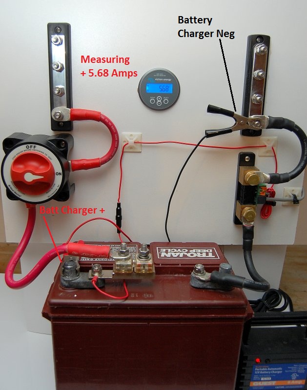
In this photo I have a Guest battery charger connected to the system. The battery monitor is reading a positive +5.68 amp charging current, as it should. Take note of the location of the black alligator clip in the next picture for a good example of why it really DOES matter where your negative system wires are connected.
Measuring Nothing !!
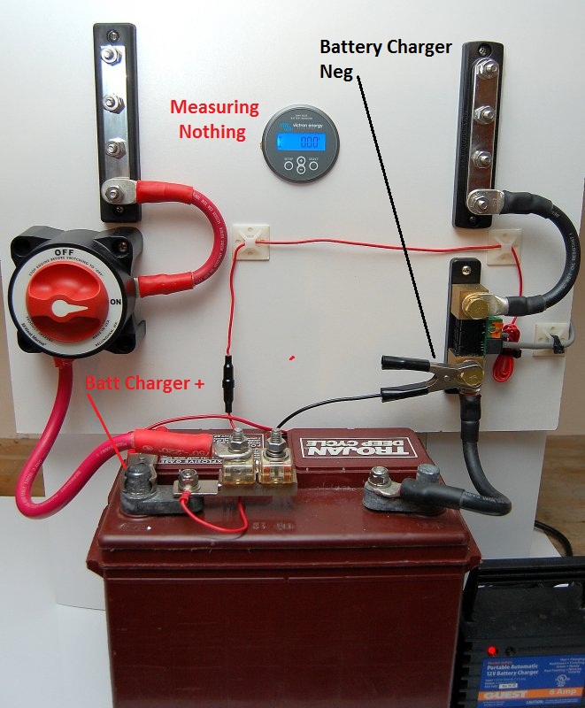
The only thing different in this photo is the location of the chargers negative lead. The charger is still pumping out about 5.68 amps but because the negative lead is on the wrong side of the shunt it cannot be captured or measured by the shunt. If it can’t be seen/captured by the shunt it can not be logged or read by the battery monitor.
IMPORTANT: Don’t jump the shunt!
Any wire that winds up on the BATTERY TERMINAL or BATTERY SIDE of the shunt I refer to as a SNEAKER WIRE.. Just say no to SNEAKER WIRES..
Whether you are drawing a load or feeding the system a charge current the negative *load wires must be on the load side of the shunt not the -BATTERY side.
NOTE: The term “load wires” applies to charging wires and discharging wires
Battery Fuses

I am a strong believer in over current protection or fusing of battery banks, even start banks on smaller auxiliary engines, despite this not being a requirement to meet in ABYC E-11.
This product is called a battery terminal fuse.. These fuses are meant to protect the wiring from dead shorts and are easy to install. I use the double version for the bank and the alternator wire. As always choose your fuses based on the wire gauge you are protecting.
Every positive wire connected to a batter should be fused within 7″ of the battery or as close as you can get. This includes inverters, alternators, battery chargers, bilge pumps or stereo memory wires.
Interestingly enough the black fuse holder for this Victron battery monitor is 7″ from the ring terminal for the battery post.
Battery Fusing Article
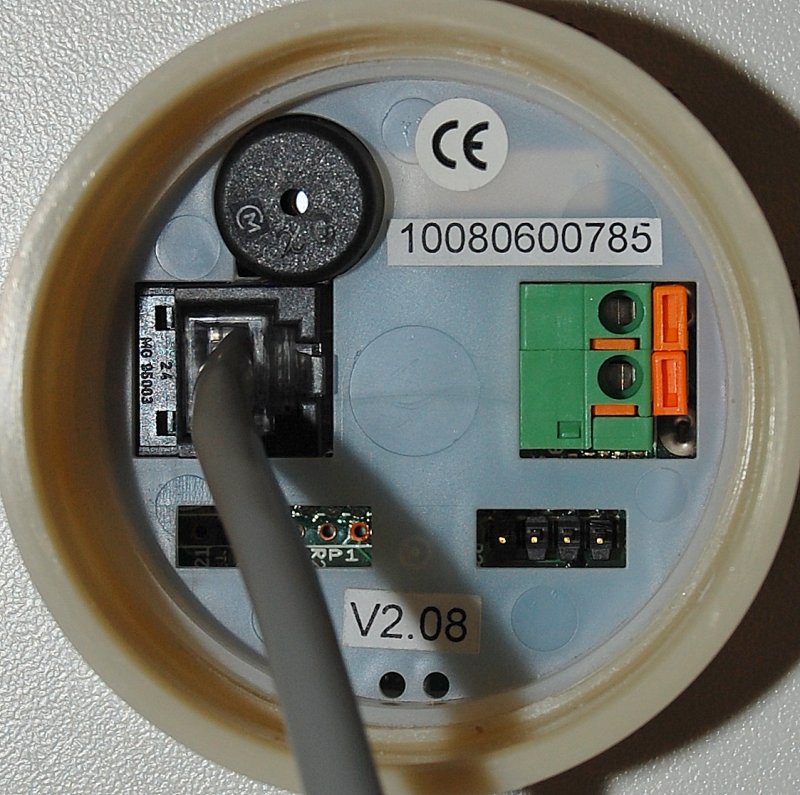
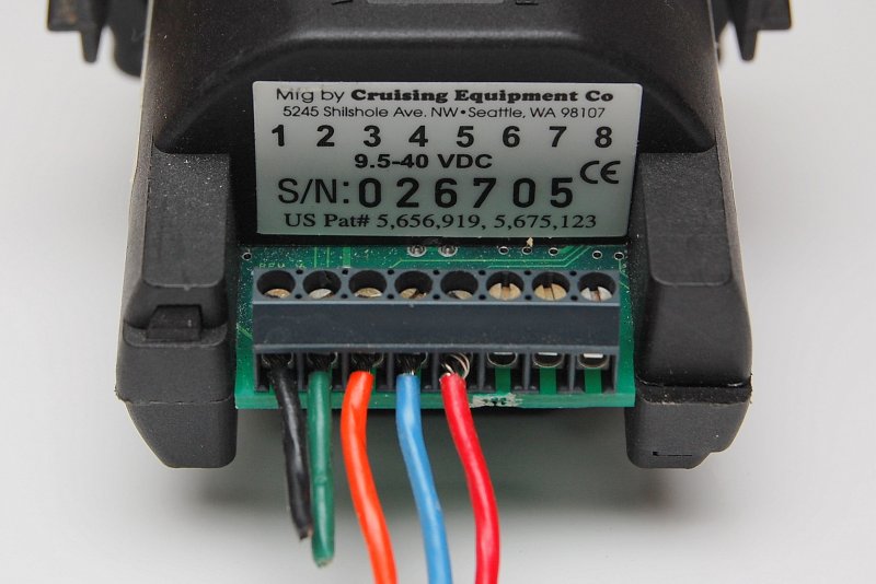
Making The Connections

This is the back of the BMV-602S. There is a port for the computer connection kit, which can be purchased at additional cost, an alarm and the UTP cable connection port.
Plug & Play
Once you have chosen your location, drilled the hole for the monitor and run the UTP cable, simply plug it in to the socket. If you can plug in a fax machine you already know how to connect the monitor to the shunt. This could not be any easier. Kudos to Victron for making this so easy!
Shunt End
Now plug the UTP cable into the shunt. Easy..
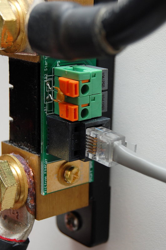
Click !
Click, that’s it!
Power Supply Wire – Pin End
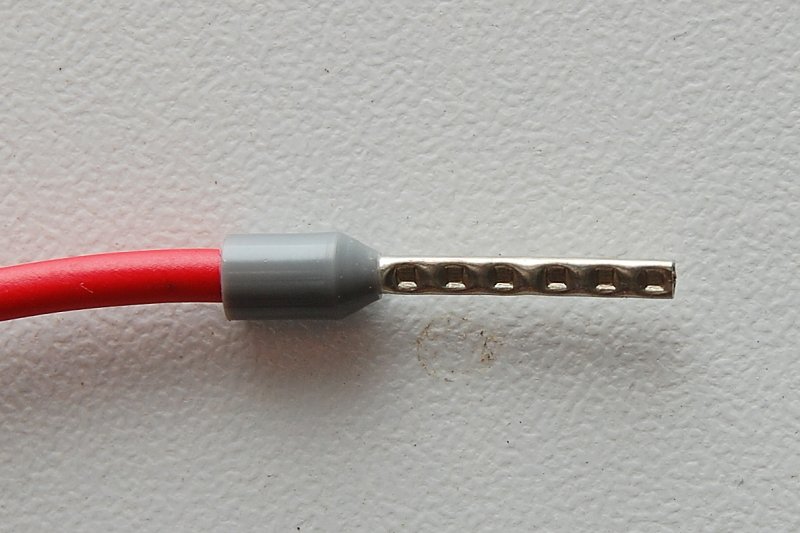
This is a close up of the crimped pin for the power supply cable. If you own a ferrule crimp-tool feel free to cut this to your desired length.
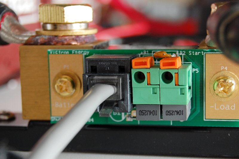
Use A Small Screw Driver

Use a small flat bladed screw driver and simply slide the orange tab towards the shunt to open the clamping mechanism. In this photo I have not yet slid the orange tab towards the shunt.
Slide Back The Orange Tab
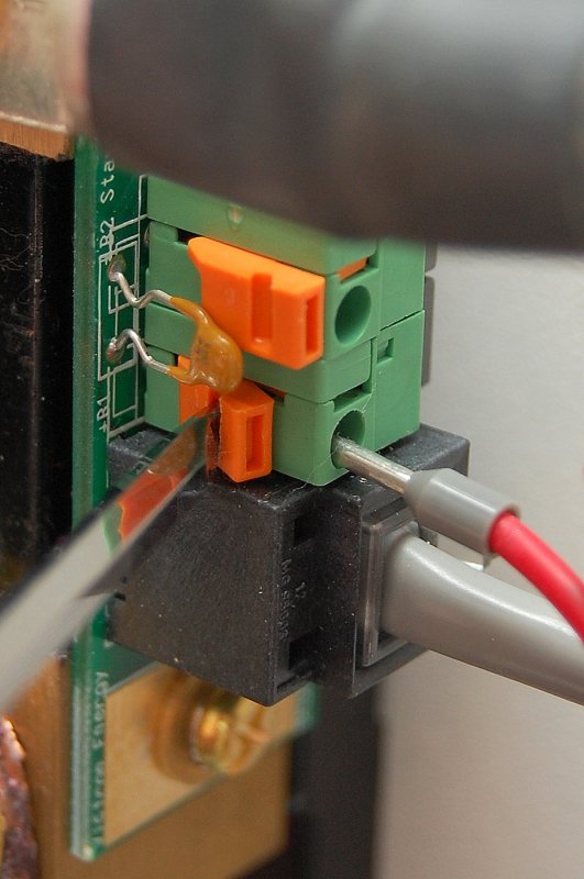
With the tab slid backwards simply push the pin into place. It will slide all the way into the socket just about up to the plastic.
Older Link 10
Here’s a prime example of why I like the Victron for simplicity. This is an older Link 10 and it requires five wires to be installed and then screwed down at the monitor end. This is certainly not difficult but requires some level of precision, access and can be a tad tedious.
The current Xantrex monitors, Link-Lite & Link-Pro, still connect exactly like the old Link 10 and on top of that they cost more money.
500A x 50mV Shunt

Rather than a shunt mounted PCB, like Victron has chosen, which offers true “plug and play” simplicity, the Link series shunts, & many others, still require wire stripping, crimping, and the physical need to manually wire the shunt. The blue & red wires from the previous photo, and not pictured here on the shunt, go to the positive battery post with in-line fuses.
Again, these are not difficult to wire just more tedious. I still have a Link-Pro on my own vessel, and I am of the opinion that the Xantrex units are slightly more robustly built, but you certainly pay for that quality, which may not even be necessary.
As of this writing the Xantrex Link-Lite cost $223.99 at Defender. That however is not the whole story. The Xantrex monitors do not come with the wire to hook it up, just the shunt. The “Xantrex communication kit” or roughly translated to as; multiple twisted-pair wire runs another $104.99 at Defender. The Victron units come complete & ready to install.
A Xantrex Link-Lite will cost you $233.99 + $104.99 = $328.98 A Victron BMV-702 will cost you about $100.00 or so less. They both will monitor the voltage of a second bank but the Victron is costs less and does more. It will also allow the connection of a computer which the Link-Lite will not do.
That being said if you don’t need to monitor the voltage of a second bank, really not all that necessary if it is just a starting or reserve bank, then Victron also offers the BMV-700 single bank monitor.
Measuring Voltage
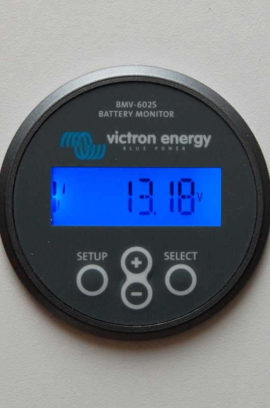
Battery monitors can display many different values on the screen including voltage, amp hours consumed, amperage, state of charge and more.
The “V” screen, as shown here, measures voltage for the house bank. This voltage reading is showing the battery being float charged.
This particular model, the Victron *BMV-602S, can monitor the voltage of two banks as can the Xantrex Link-Pro & Link-Lite models from Xantrex.
*NOTE: The BMV602S has been replaced by the BMV-702. The BMV712 adds Bluetooth programming and communication
Measuring Voltage Bank 2
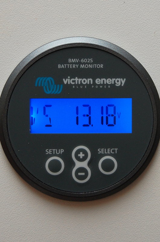
The “VS” screen tells you the voltage of a second bank. Seeing as I used one battery for this illustration the meter is showing the same voltage as the the “V” screen.
I should mention that there have been a couple of people on the boating forums complaining that the V & VS screens, even when fed from the same source voltage are not in sync or well calibrated. This sample happens to be properly calibrated. An experienced sailor and electrical engineer on SailboatOwners.com has had two units with voltage readings from .01 – .03 volts off when sensed from the identical source.
Is a variance of .01 to .03 volts a big deal? No, not at all, but I just wanted to make you aware so that you don’t panic if your V & VS screens do not completely agree. Victron might need to do some better QC with the V & VS screen readings!
Measuring Amps At Rest
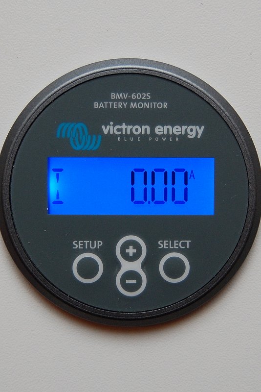
The “I” screen shows current in/out. This shot is showing no loads or charge current.
Measuring Current Flow
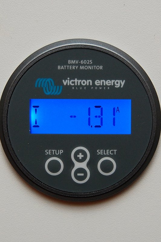
This “I” screen shot shows the monitor measuring a negative load. A negative load is denoted by the – symbol.
Measuring Charge Current
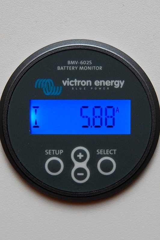
This screen shows a charging current as denoted by the lack of the – symbol..
Amp Hours Consumed
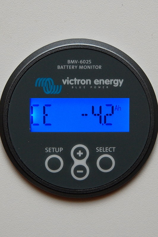
This is the CE or Consumed Energy screen. It shows the amount of amp hours consumed from the battery. After the battery receives a full charge this readout resets to 0.0 Ah denoting a fully synchronized monitor.
If you draw a current of 10 amps for a period of 4 hours you will show -40 Ah on the CE screen.
State of Charge
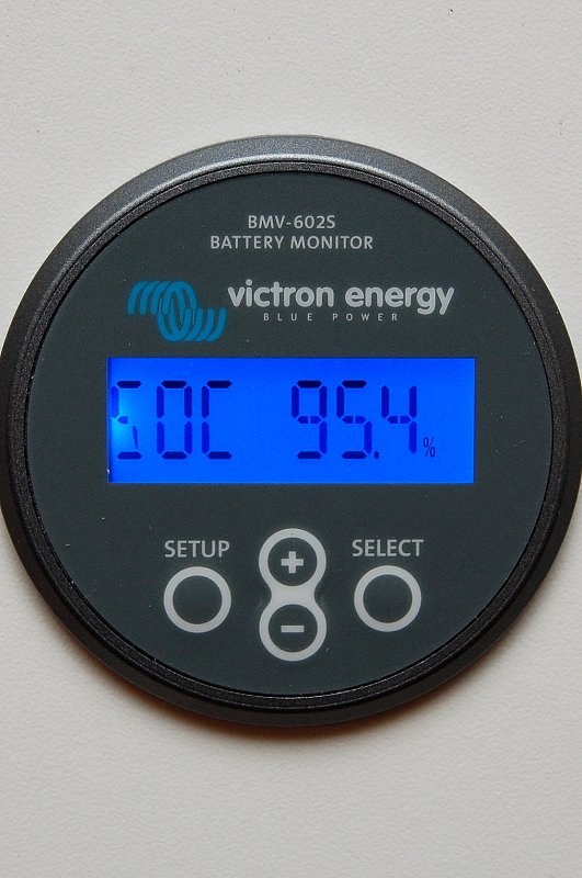
This is the SOC or State-of-charge screen. This screen is the best way to monitor the SOC of the battery with this monitor. This screen is only useful provided you have programmed the monitor correctly, it’s synchronizing the way it should, and is wired properly. This readout calculates the amount of energy available in the battery and is Peukert & CEF / Charge Efficiency & capacity corrected. The screen ranges from 0% = dead to 100% = full.
Counting amp hours is ok but is most often is not an accurate reflection of the true state of charge of the battery. For example if the battery is drawn down heavily & at a high rate of current you will get less usable Ah’s than its rating. If drawn slower than the 20 hour rating you can get more Ah’s out of it.
The SOC screen computes for the Peukert exponent and CEF, the Ah screen does not.
Please take the time to read the manual for these monitors as they are generally more difficult to program and master than the actual installation!
To keep your monitor accurate:
- Wire it correctly
- Program an accurate Peukert exponent for the bank
- Program an accurate Ah capacity for your bank
- Program an accurate charge efficiency
- Turn OFF or program around auto-sync
- Use manual known-full resets
- Reset as often as possible when you know the bank is full
- Each year find your new 20 hour Ah capacity or reduce capacity with a hip-shoot guess
IMPORTANT: Reserve Capacity, Reserve Minutes or an RC rating are NOT the 20 hour Ah capacity!
NOTE: Most healthy flooded lead acid batteries need 115% or more charge put back in, compared to what you took out. This means a charge efficiency of 85% is often more accurate than 90%. Check with your battery manufacturer to get the most accurate charge efficiency number you can get. For more information & detail on this complicated subject see: Programming A Battery Monitor
Good luck & happy boating!
Let’s Keep This Site Running!
Like what you saw or read? Would you like to see more articles like this? Is so feel free to donate, support the site and keep it growing. I am trying my hardest to keep this information FREE. If you liked it, learned from it or I saved you some money feel free to make a small donation, that’s all I ask.