DIY LiFePo4 On Boats
Last edit;3/26/23:The base of this article was written a number of years ago (2010) but this does not mean the information here is outdated. We have been keeping it updated and have added to it when ever we had the time. This article deals with DIY LIFePo4 builds.
The Cells arrive -April 2009

What do we recommend for DIY LFP Sourcing?
 18650 Battery store stocks a large assortment of DIY Cells & BMS’s. They have true EV Grade and occasionally, honestly rated B grade cells at great prices. Because they are in the US you get you cells in days not months. Taking matters into your own hands & importing directly from China you are very, very likely to get reject grade cells.
Buy DIY LifePo4 Components/Cells
Victron has the most programmable equipment to pair with LiFePo4. Our partner Bay Marine Supply has excellent pricing and supports what they sell!
Buy Victron Inverters or Inverter/Chargers
Where can I Find the test equipment you use?
Buy MHT Recommended Test Equipment
Where does the information in the article stem from?
Ever since I began the foray into LiFePO4 batteries readers of MarineHowTo.com have been asking for more information about these cells. My experience and background with LFP date back to approximately 2007 when I began researching this technology and reading every white paper I could get my hands on. I quickly noted a complete lack of data for off-grid or fractional “C” type use.
Fractional C Use:
Utilizing a LiFePo4 battery at discharge and recharge rates that are typically below suggested safe maximum discharge and recharge rates, as one will often do with the house bank battery on a boat.
This lack of available data resulted in setting up a test lab at Compass Marine Inc. (parent company of MarineHowTo.com).
With the test equipment in place, we then began experimenting with bare cells, 12V packs, charging schemes, balancing schemes, cell matching, float capacity loss testing, over-current protection testing, storage SOC & degradation, over-charging, charging at various C rates, Peukert testing, etc. etc. etc. etc. etc.. Over the last 10+ years, I have many thousands of hours of testing LFP cells in regards to house bank or off-grid type use. In the process I’ve destroyed well in excess of $4k in LFP cells, both in prismatic and cylindrical form factors. This testing was only done because years ago it did not exist and we had to do the work ourselves to identify potential issues. The testing has given us a better understanding of how these cells behave and what charging & use practices may be damaging on a short term basis or long term.
I’m also an ABYC electrical systems specialist who works on boats professionally (retired 2021). Compass Marine Inc. was a manufacturer of marine products and components such as alternators and custom LFP batteries. We specialize & focus on energy management systems for both design/engineering and installation. I am also an active member of the ABYC Li-Ion Battery committee that developed the safety standards for Li-Ion batteries.
Beyond all that we’ve had a 400Ah LiFePo4 bank installed and in-use on our own sail boat since early2010. The cells in this bank were manufactured on May 10 of 2009. I am a huge fan of LFP banks, for many reasons. To put it bluntly I really, really love them and they are a complete game-changer.
IMPORTANT:
#1 – The advice here is not intended to get you to buy LiFePo4 batteries from us, it is for you to learn something from so you can get what you paid for when you finally make your own decision. Above all else I don’t want to see readers of MHT get screwed over. This is why we provide links to reputable vendors. We don’t want to see you ruin a multi-thousand dollar investment, as many LFP pioneers before you have done.
#2 – The ABYC Li-Ion Battery Standard E-13 has finally been published.
#3 LFP Safety-While it is widely known that LiFePo4 is the safest of the Li-Ion chemistries. I still , 12 tears after authoring this article ,offer the reader challenge below..
Reader Challenge:
I will continue to offer a challenge that I have been offering now for 12+ years on the Internet and that is; the first person to bring me an image of a lithium iron phosphate cell, properly installed, that erupted into flames or resulted in an explosion due to overcharging, I will pay them$50 cash for that image! In 12+ years not one person has been able to bring me such an image…This is because LiFePo4 is an extremely safe chemistry.
LFP Design & Consultation:
Compass Marine Inc. / MarineHowTo.com no longer does consulting or design work for DIY’s. We are still consulting to certified industry professionals.
Why no DIY consulting? Simple, because this is consulting not education. In order to qualify for consulting your pre-requsite is having a very good grasp on all things electrical and having passed ABYC electrical training. You really can’t afford to pay us to educate you on the basics. These are things you should already know such as Ohm’s law Kirchoff law, ABYC standards etc.. DIY’s did this to themselves by arguing our consulting was too expensive, then refusing to pay the bill.
This article is for INFORMATIONAL & EDUCATIONAL PURPOSES ONLY
WARNING / DIY BUILDS:
I do not believe LiFePO4 is ready for mass DIY prime time builds. Read with caution, and especially focus on the things that you don’t want to hear rather than only what you want to hear. Once you are done reading this, and it makes sense to you, continue your research.DIY builds are easily doable if you have a strong understanding of things electrical.
While this article is meant to be very basic, and get you a basic level of understanding of LFP, the science side of it matters too. We strongly recommend that you also read Eric Bretscher’s site for the science side of LFP:
Nordkyn Design LiFePO4 Article
With this article, and Eric’s information, you’ll be well on your way to understanding how to build & use a LiFePo4 marine system without ruining it prematurely.
“But Rod, People on the internet made it sound so easy?“
Hey, lets face it, everyone gets excited with their new toys, and likes to talk about them, but we urge you to please do more research. In other-words, don’t jump to conclusions based on scant information, where large sums of money are involved.
YOUR RESEARCH DOES NOT END WITH THIS ARTICLE
What this article will discuss, and what it won’t discuss:
1- This is meant as a general overview of DIY LiFePO4 batteries (no other Li-Ion chemistry) for use as house banks on boats only. I will sometimes refer to this type of use as “fractional C” use.
2- It is the sharing of my learning, experimentation & installation/implementation of LiFePO4 batteries on boats. Contrary to what some folks think, I do not consider myself an expert on the subject of LiFePO4. If even the Chinese manufacturers, research institutions etc. don’t fully understand this technology, inside and out, how can I?
3- This article will not show you every little detail to build your own bank or give you every last ounce of detail & specific wiring diagrams. It is my belief that those final details need to be ironed out by whomever decides to DIY with the specific equipment chosen. LFP systems can be very application specific.
4- This article is not a suggestion or an endorsement for widespread DIY builds of LiFePO4 batteries. For those with the capabilities, & test equipment to confirm cell quality, by all means, have at it.
5- LiFePO4 can put a big dent in your wallet if not done in a manner that protects the cells from abuse. Even many commercially available BMS systems are only protecting the cells at a catastrophic level to prevent thermal runaway etc.. Many BMS’s are not designed to yield the cycle life owners may also desire. This article will delve into the various ways to manage a DIY build of cells, so you can extract an acceptable cycle life for your $$$.
What’s In The Box..?
The Shipment:
These Winston 400Ah cells came from Balqon Corp in California, a company which was directly owned by Winston Battery. Winston closed Balqon Corp in 2010… My suggestion for buying LFP prismatic cells todayis to try and find USA stock, or a dealer such as Current Connected who routinely deals with the Chinese as an import agent. Reputable prismatic cells such as CALB, Sinopoly, Winston, GBS or some of the aluminum cased cells such as EVE or CATL, GANFENG etc. are also EXCELLENT
Plastic vs. Aluminum Prismatics
Back in 2007 when I began planning my LFP build there were only a few manufacturers of LFP prismatic cells; Thundersky (Winston) GBS and CALB. Technology has improved and today I would suggest Aluminum encased Prismatics. There are a lot of manufacturers to choose from with CATL, EVE, Ganfeng & REPT being the most popular. Do not buy these cells off Aliexpress what ever you do.This photo sums up what LFP was back in 2009 vs. today. The blue plastic cells (left) are CALB SE series 100Ah cells. The cells on the right are EVE 304Ah. Ignore the mess of wires these cells were in the process of testing, top balancing etc.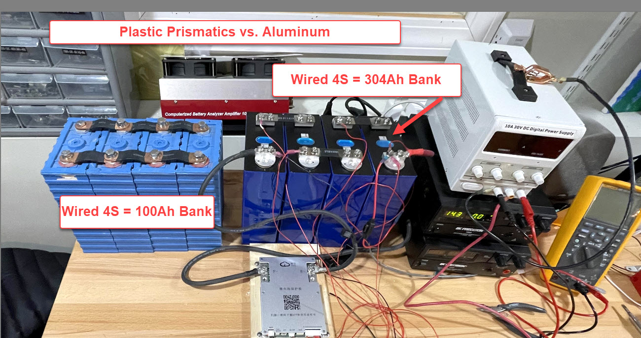
Who do we recommend for DIY Cell Sourcing?
18650 Battery Store (stocks a good selection of EV /Grade A cells)
Buy LFP Cells/Components – 18650 Battery Store
If you wish to conduct a DIY build, we strongly recommend purchasing cells From 18650 battery Store in Georgia. Taking matters into your own hands & importing directly from China is very, very likely to get you reject grade junk cells.
LiFePO4
The Cells

The Li-Ion chemistry chosen for this bank is called Lithium (Li) Ferro/Iron (Fe) Phosphate (PO4), LiFePO4 or LFP for short. There are a few variations on this chemistry such as LiFeMnPO4 & LiFeYPO4 but the end result is still essentially an LFP bank that has the same inherently safe characteristics. For this build I chose four 400Ah Winston LFP prismatic cells, and the bank is set up in a 4S or 4 series cells configuration.
What the heck is 4S?
4S just means four 3.2V cells in series to make a 12V nominal pack. The pack/bank is really closer to a 13.3V pack as the resting & nominally loaded cruising voltage of these cells is around 13.2V – 13.35V.
If you want to do other than a 4S configuration the cells are typically connected in parallel first and then in series. Parallel first is done so that you only need to monitor 4 cell voltages for a 12V nominal pack. The parallel cells stay naturally balanced which means a less expensive BMS can often be used. If you were to choose series-first you would require more cell level monitoring. The nomenclature system you will most often see for a 12V nominal house bank is as follows;
4S = Four Series Cells
2P4S = Two Parallel Cells / Four Series Cells
3P4S = Three Parallel Cells/ Four Series Cells
4P4S = Four Parallel Cells/ Four Series Cells
etc. etc..
There are many ways to configure LiFePO4 Cells in series or in parallel/series. When possible, I tend to prefer the simplicity of a 4S configuration, if that cell size works for the desired Ah capacity. 4S requires less overall connections and less work when doing cell balancing. Some would argue that if a cell is ruined with a 2P4S bank you could re-wire it and use the remaining cells. At sea? While anything is possible, I personally prefer the simplicity of a reserve or start/reserve lead acid bank as opposed to a complete LFP re-configuration at sea. A lead acid reserve bank or start/reserve allows you to take the LFP bank off-line while addressing any potential issue. Rewiring & re-balancing an LFP bank at sea is not a task you’d ideally want to perform.
LiFePo4 Battery Bank Type Definitions:
Factory Integrated:
A lithium battery designed to work as a factory integrated system including the charge sources
System Integrated Lithium-Ion Battery:
A lithium battery system with the capability of system interaction/communication with external charge sources, vessel loads, alarms or safety systems.
Drop-In Lithium-Ion Battery:
A self-contained lithium battery, with or without an integral BMS which lacks external system communication with charge sources, vessel loads, alarms or safety systems.
Drop-In Batteries for Boats Article
Examples:
Factory Integrated Lithium-Ion System:
Victron & Mastervolt are about as close as it gets because they sell both the charge sources and the LFP batteries as a factory integrated system.
System Integrated Lithium-Ion System:
Lithionics ex: Genasun & well executed DIY – Designed to work with third party products and can communicate with them.
Drop-In Lithium-Ion:
If the internal BMS is sealed, and the battery can’t tell an external charge source when to stop charging or a load to stop discharging, then this is considered a drop-in battery. Whether or not a drop-in batteries are well suited for your use will depend upon many factors. see article link above.
There are three basic options of getting LFP on your boat, with DIY being the least expensive, and most technical. The categories are:
DIY Builds:
This is a real cost saver but is not for the faint of heart or the limited skill DIY’er. In a DIY build you source the cells, confirm the cells are well matched for Ah capacity & Internal resistance,choose all the components, choose the BMS, wire and assemble everything, balance the pack and chose chargers, solar or alternator regulators that can be programmed to suit LFP. A well executed DIY build, and there are many of them out there, is a a time consuming project to do correctly. If you have the gumption to forge ahead, it is method that can save over 50% of the cost of a factory made bank.
Marine Specific Factory Made LFP Systems:
Lithionics/OPE-Li3, Victron & Mastervolt all build LiFePO4 batteries for marine specific applications. These systems are well engineered, well executed yet also at or near the top end of the pricing spectrum. You do however tend to “get what you pay for“. If you want LFP and don’t have the ability to DIY, any of these three companies make excellent products.
What About Drop-In LiFePO4 Batteries?
Read This Article:
Drop-In LiFePo4 – Be an Educated Consumer
LiFePO4 vs. Lead – Pro’s & Con’s
No article would be complete without pro’s & cons comparisons between lead and LFP.
LiFePO4 Pro’s:
CYCLE LIFE:
Most decent LFP cells today can deliver 2000+cycles to 100% DOD (depth of discharge). If you compare the best AGM batteries to LFP you’ll find that reputable manufactures such as Enersys/Odyssey claim just 400 *lab rated cycles to 80% DOD. Please understand that just like lead acid “cycle life claims” this testing is not done in a real world applicable environment. In cycle testing LFP they are never floated, never over-absorbed, never held at a high SOC for long periods, never over discharged, and they cycle up and down in an automated cushy 77F to 80F (25C) test environment.. Vary any of those parameters and you may not see the same results. With the low prices of prismatic cells these days who cares if you don’t get the rating they are still much cheaper than AGM…
The average lead acid battery on boats is often dead well before 150 – 200 cycles and they rarely if ever even come close to the “lab rated” cycles. They are usually dead well before 50% of the lab rated cycles have been used. Do the math on your own bank, be honest about it, and see how many cycles you had, to 50% SOC, before your bank needed replacement. Most boat owners are shocked when they do this math.
At Compass Marine Inc. we have never seen a single lead acid battery bank hit its lab rating in the marine environment. This is especially true on cruising boats. Lead acid lab numbers are fairy-tale ratings when applied to real world cycling behavior. House banks on boats are simply not being used in the same manner that lead acid or LFP factories test them. Both lead and LFP cycle testing does not allow the batteries live in hot engine rooms, over-absorb them nor do they ever float them when testing for cycle-life.
The bank featured in this article has now surpassed 2200 cycles most all of which havw=e been to 80%DoD and close to 100 cycles to 0%…It still delivers 100% of its rating.
USABLE CAPACITY RANGE:
80% of an LFP banks capacity is fully usable, when cycling20% DOD. With lead acid you often have just 30-35% usable capacity (50% SOC to 80-85% SOC) due to charge acceptance current limiting. With solar or alternative energy systems on lead acid you can get more daily usable capacity but it requires a lot of PV real estate to push into the charge acceptance taper. With LFP the current limiting or acceptance taper is very, very short in duration, even at relatively low 12V nominal pack charging voltages of 13.8V – 14.0V (3.45VPC to 3.5VPC) this duration can be as short as 10-30 minutes depending upon charge rate. If you increase the voltage of the pack towards 3.6VPC the CV duration almost entirely vanishes.
CHARGING SPEED:
Very short current taper even with large current sources. With low current charging, such as solar, you can charge to nearly full before even attaining CV/absorption voltage. This of course is entirely dependent on your charging voltage and your current source. On my own boat I charge the 400Ah LFP bank at approx 145A to 13.8V and the current taper lasts only 30-35 minutes. Compare that to hours and hours of current-limited charging using a 145A charge source on 400Ah of lead acid batteries. With a small charge current source, like a small PV system or wind, you can hit 99%+ SOC before the constant voltage (CV) stage is attained or before any current limiting can even occur. This means a 100% acceptance rate all the way to 99% + SOC. My 400Ah bank literally has to be chock full before the solar array can even get it to 13.8V. These batteries can take immense current, and charge extremely fast, but really tend to do extremely well with .3C to .5C in charge current.
WEIGHT/SPACE:
Less than half the weight of lead, Ah to Ah, and almost always more compact. The 400Ah bank in this article weighs 134 pounds less than a 400Ah lead acid bank. However, to equal the usable capacity of a 400Ah LFP bank, on my own boat, I would have needed approx 900Ah’s of lead acid. This makes the 400Ah LFP bank approx 400 pounds lighter than the equivalent usable capacity in lead acid.
GET OUT THE DEAD LEAD:
The term “dead lead” is s term I coined in my electrical seminars. The typical lead acid bank consists of 65-70% of the weight being comprised of “dead lead” or the excess lead you carry around but that you can not use. If you have a usable capacity of just 30-35% of the bank, when out cruising, this means that you are carrying around 65-70% of that weight in unusable “dead lead” capacity. This 400Ah LFP bank weighs 130 pounds & 80% of it is fully usable or 100% if you don’t mind giving up a few cycles. If you stop discharging at 80% DoD this means just 20% of ithe bank is not actively usable or you simply don’t want to use it for optimal cycle longevity. As a result, we carry around a measly 26 pounds of unusable battery on our 36 footer.
Lets go back to usable capacity for a moment. If I wanted to equal the usable capacity of this 400Ah LFP bank in lead, I would need the equivalent of 8 GC2 6V golf cart batteries or approx 900Ah’s. 35% of 900Ah is a usable capacity of 315Ah’s. 80% of the 400Ah LFP bank is a usable capacity or 320 Ah’s. A 900Ah lead acid bank weighs 520 pounds. If I used just 35% of that bank, as I would when out cruising, then I would be hauling around 338 pounds of “dead lead” or 338 pounds of unusable Ah capacity. Twenty six pounds of unused LFP or 338 pounds of “dead lead“..?? Points to ponder. Again, if you have a large PV system or ample alternative energy systems then you can use more of the lead bank in daily cycling. On our boat, and many like it, this was not an option without making her look like a clown car of solar. My wife put her foot down on more solar many years ago and can’t even stand the look of the moderate PV system we have now.
STEADY VOLTAGE:
LFP banks have a very strong & fnearly flat charge & discharge curve with a very steep & fast rise (charge knee) or drop (discharge knee) at either end. These ends are called the “knee’s”. LFP cells will maintain voltages well above that of any fully charged lead acid bank, and remain very close to their 3.3VPC / 13.2V nominal voltage level, and hold quite steady voltages, with moderate change, almost all the way to 80% DOD. They will maintain a very tight voltage range even under “normal/typical” house loads. Espar heaters, refrigeration, water-makers etc. will all perform better. Equipment likes higher voltages. Even bilge pumps will pump more water. Voltage sag that can drop out electronics during bow thruster or windlass use is almost entirely eliminated so long as you have a BMS that can handle the high in-rush loads.
CHARGING EFFICIENCY:
Charge efficiency is also referred to as the Coulombic efficiency. These batteries are as near 100% efficient as I have ever seen on the CMI test bench. Take 200Ah’s out and put 200 Ah’s back in and you hit the voltage and net accepted current at almost the exact same Ah’s out to Ah’s in. Until LFP I had never witnessed anything like this, even with the best AGM’s. Lead acid ranges from 70% to as high as 90% +/- efficient but you still need to put back in 10-30% more than you took out, and this is with “healthy” lead acid batteries. As they sulfate the charge efficiency or Coulombic efficiency gets even worse.
NO NEED TO RECHARGE TO 100% SoC:
We know the Achilles heel of lead acid banks on cruising boats is almost always sulfation. In order to fend off the effects of sulfation we need to charge them to 100% SoC as often as possible. This proves very difficult for many cruisers unless your boat resides at a dock after each use or sits on a mooring with an adequate solar system. LFP batteries do not need to get back to 100% SoC frequently, like lead acid does. In fact, keeping LiFePO4 cells at 100% SoC can actually negatively impact cycle life. Not needing to get back to 100% SoC, on a routine basis, is a major win for LFP. When we come back from a cruise, and our battery is at 50% SoC, I don’t care. I simply shut down the boat, and the solar and go home. LFP batteries actually prefer to sit at 30-65% SoC rather than at 100% SoC. As I mentioned earlier, this is a mental paradigm shift owners of LFP will need to overcome in our human behavior/thinking around our batteries. The lead acid mindset of 100% SoC often or continual floating in the upper SoC register will be best to be mentally reprogrammed.
SULFATION, WHAT’S THAT?
Sulfation is by far and away the cancer and #1 killer of lead acid batteries on cruising boats. LFP batteries do not sulfate so there is no need or worry to constantly get back to 100% SOC before you leave your boat. LFP batteries actually prefer to be left at mid range SOC rather than full. Enjoy that sail home, without the motor.
SAFER Li-Ion TECHNOLOGY:
Without question LFP is one of the safest of the Li-Ion battery formats. Many argue, and these arguments have certainly been well made, LiFePO4 is as safe or safer than lead acid. ALL BATTERIES ARE DANGEROUS, let us not forget that.
As Li-Ion technology goes LiFePO4 is currently one of the safest. Remember we are surrounded every day by far more volatile Li-Ion technologies in computers, iPads, iPods, tablets, video games, cell phones and even cordless tools. LFP is less energy dense than other more volatile Li-Ion formats, but when compared to lead acid everything looks energy dense. We have no need on boats for “dream-liner” level energy density, thus we normally use the considerably safer LiFePO4/LFP technology not LiCoO2 like Boeing used. If you believe the Li-Ion chemistries of LiCoO2 & LiFePO4 are the same risk level I would suggest you stick with lead acid until you do a lot more research.
I think this video done by Sinopoly can sum up the safety of LFP technology. Those crazy Chinese guys shot, burned, shorted and cooked these cells. Please do not attempt this stuff at home. Take note that a single 60Ah 3.2V cell can throw in excess of 1800A of current into a dead short. WOW! None of the testers got acid burns, were blinded or went home with holes in their clothes.
:
That said and shown, it is a fallacy & myth to believe that LiFePO4 batteries can’t achieve thermal run away and catch fire. LiFePO4 batteries can catch fire and they can suffer from thermal run-away it is just much less common than other Li-Ion chemistries. If an LFP battery does catch fire, you don’t want to be near it.
Lead Acid is safer?
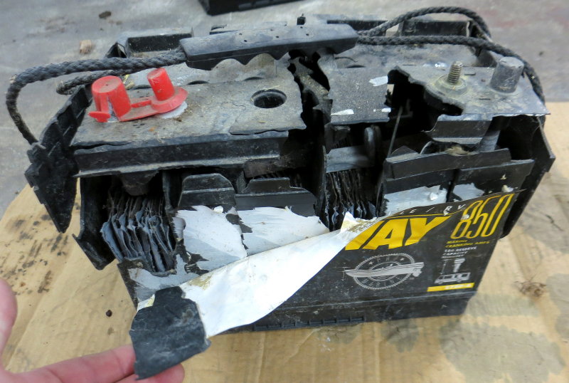
Let’s be real, no battery technology is 100% safe…. Stupid charging practices, like using an automotive battery charger on a boat, can wind up with a situation like this.
Take a guess at what the battery acid did to the inside of this boat when this lead acid battery went KA-BOOM………!!
Yes, BOOM, and its not LiFePO4!!! (wink)
LiFePO4 Con’s
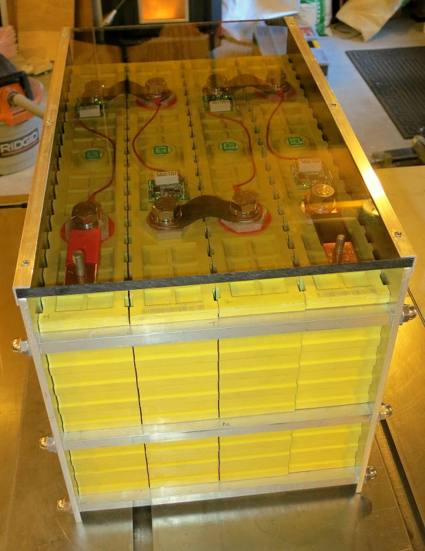
PHOTO: In this photo I have constructed my cell compression case. Prismatic LFP banks need what is called cell compression cases so that in an overcharge event the cell bulging or swelling will be controlled. For this bank 1/4″ 6061 aluminum was chosen as it is easy to work with & non flammable. The cover is 3/8″ Polycarbonate.
LifePO4 is tremendous technology but there are also some areas that needs strong consideration;
LiFePO4 Cons:
OVER CHARGING:
LFP batteries can be quickly compromised, have the capacity diminished or even destroyed if abusively over-charged. Unlike lead batteries over charging does not just gas off some electrolyte that can be replaced, it can literally ruin the battery. A lead acid battery will suffer some permanent capacity loss from chronic over charging, but can survive this, an LFP battery will usually not survive this. This means proper charging and a cell level BMS system to ensure that over charging of the cells can not happen. Please under stand however that over-charging is not just about voltage.
DURATION AT TARGET VOLTAGE (Over-Absorbing):
Most lead acid designed charge sources can hold the absorption voltage stage more than long enough to cause long term damage or eat into some cycle life capacity of your expensive LFP cells. Some LFP manufacturers are now starting to understand this point, when selling into a lead-acid charger environment, and have reduced recommended max charging voltages accordingly. Of course, some others have not. The quality of the cells used inside the battery also play a major role as to how well they deal with constant voltage being held longer than is necessary.
LiFePO4 cells are optimally charged to 100% SoC, then charging is terminated, stopped or dropped to a voltage level that will not cause long term harm. This was the original design of the chemistry. This does not happen with far too many lead-acid designed chargers, so you as an owner will need to choose charge sources that can be carefully programmed to limit the constant voltage duration. Victron makes excellent equipment that’s fully programable for LFP.
Below is a study conducted at a University using the same exact prismatic cells. They charged the cells to 4.0V then discharged to 0% then repeated this for 950 cycles. The cells survived 950 complete 100% discharge & recharge cycles. The difference here being the charging was 100% terminated/stopped when 4.00VPC was reached and the discharge current automatically turned on. This means the cells were only above 3.45VPC for a very, very brief period on each cycle and were never held continuously at 100% SoC..Most LFP cells have a max safe voltage of 3.65VPC or 14.6V Winston cells can be charged to 4.0V and survive in lab testing but for routine use Winston also advises a max of 3.65VPC.
The relationship between target voltage, duration at target voltage + charge current is where damage can occur. When setting up an LFP system these three factors can’t be ignored;
Target Charge Voltage
Duration the Charge Source Maintains/Holds Target Voltage
Charge Rate
These three items go hand in hand with LFP.
Charging LFP is simple – Charge to target voltage then stop charging or drop to a safe float voltage.
OVER DISCHARGING:
Just like over charging over discharging can actually result in a polarity reversal and destruction of the cells. A lead acid battery may suffer some permanent capacity loss but can easily survive this, an LFP battery will not. This is another reason why an LFP system should be designed and installed as a “system“..
CHARGING BELOW FREEZING:
LFP cells should really not be charged at temps below 32F/0C. Again, this is another mistake that can lead to lithium plating. LiFePo4 can be discharged below the freezing point but should not be charged at the typical charge rate.
There is some confusion out there surrounding the LiFeYPo4/ Winston cells. Winston claims that the addition of Yttrium allows the cells to be “charged” at temps as low as -40ºF. I have asked Winston & their old US distributor Balqon, via email on multiple occasions, to furnish or name any third party testing that confirms it is safe to charge LiFeYPo4 cells at temps below 32ºF/0ºC. All I’ve received is dead silence.
Until I see some verified & legitimate third party or University level sub 32ºF/0ºC testing I am holding steady that you should avoid this temp range for charging. If anyone has a white paper I missed on cold weather charging of LiFeYPO4 please forward it along.
CELL BALANCING:
Keeping series LPF cells balanced is of prime concern because it is high or low voltages that can ruin LFP cells. In LFP cells we have what are referred to as the upper knee and the lower knee.
What is a “knee”?
The upper and lower knees are where the cell hits full/empty and the voltage trend changes sharply upwards, in hockey stick fashion, or sinks like a rock. Over discharging and over charging an unbalanced pack is where many LFP cells are destroyed. One minute the bank is delivering or accepting massive amounts of current and the next minute a cell has gone under voltage or over voltage and a cell hockey sticks or falls off the cliff before the other cells do.
If one cell becomes out of balance, or the pack was built with poorly matched cells, one cell can hit full before the rest of the cells do and this cell can be damaged or ruined. Cell balancing is most critical when pushing or using high charging voltages, eg; 3.60 – 3.65 VPC or where you don’t know the internal resistance or cell capacities in a DIY built bank. In my experience, with properly matched LFP cells, these high charging voltages are simply unnecessary for fractional C / house bank use. Charging these cells to more than 14.0V, when they are properly matched, is really not necessary and only leads you closer into the danger zone, especially, if the cells were to drift or become out of balance.
Cell drift is why individual cell level monitoring, of per-cell voltage, is necessary in a good pack design. Pack voltage alone tells you nothing about an individual cell going off early, only what the overall pack voltage is. A good BMS (battery management system) will cut off charging well before any damage can be done to an individual cell.
Pack Level Voltage Monitoring Can Be Misleading:
Why?
3.65V + 3.65V + 3.65V + 3.65V=14.6V
But
4.2V + 3.6V + 3.45 + 3.35V=14.6V
FLOAT CHARGING:
Float Charging – A continual charge voltage applied to the battery that is in excess of it’s natural resting 100% SoC voltage.
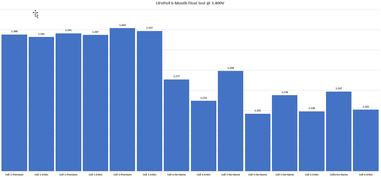
LFP batteries are not lead acid batteries and they were not designed nor intended to be “float charged“, in the typical lead acid sense (definition above). There is scant data on float charging LFP cells. At CMI we have two years of standby testing (see below) on LFP and unfortunately the data collected is all over the map. While we have a few premium branded LFP cylindrical 18650 cells that suffered zero capacity changes, after being held at 3.400V (13.6V for a 12V nominal bank) 24/7, for six months continuously, we also have capacity losses holding the same voltage on counterfeit cells and no-name LFP cylindrical cells exceeding 16%. We also have an 11% Capacity loss on some CALB SE prismatic cells from leaving them at 100% SOC and letting them sit for 12 months. In other-words the data is confusing at best and our float life testing here is still on-going.
Lack of a Definition for “Floating” LFP?
Unfortunately there is no real definition for a voltage setting that is not holding an LFP battery at a voltage above the natural resting 100% SoC point, as we do with lead acid. There are really actually two types of voltages necessary for LFP;
Storage Voltage:
A voltage setting, usually programmed using the float voltage setting on a lead-acid based charger, that results in the battery discharging to approximately 50% SoC (or a mid-range SoC) then being held there. A storage voltage would ideally be used anytime the batteries will not be used for any more than a a few weeks or so.Update: Since authoring this article in 2010 Victron has now added a storage voltage to many of its chargers.Yay Victron!
Standby Voltage:
A voltage setting, usually programmed using the float voltage settings on a lead acid charger. This voltage should be one that results in the battery discharging to just below the full charge point of the battery or 90% SoC to 98% SoC, an being held there.
As can be seen “float” can be complicated with LFP. LFP batteries ideally need two differing types of voltages storage & standby but not “float“, in the lead acid sense, where we purposely hold the battery above the 100% SoC point.
Look at any of your tablets, cell phones iDevices etc. and they all terminate charge when the battery is full. They cut back in when battery terminal voltage has fallen to a preset level, but they do not hold a high voltage on a full battery.
Floating LFP is a certainly a complex subject with scant data. Bottom line is to avoid floating LFP banks if you can, but a standby or storage voltage setting can be used.. For a typical standby voltage you would be best to be below 13.6V or 3.400VPC. Some have argued that a continual standby voltage of 3.35VPC or lower (13.4V for a 12V nominal bank) is not badly damaging over the long haul, but it may be, so a storage voltage should also be considered as a longer term option.
Please understand that any voltage below the 100% SoC point, of the LFP battery, would not be considered “floating” it. If using a standby voltage at say 3.35V per cell, the current into the battery will end up at 0A and be slightly below the 100% SoC point.
Unfortunately, we don’t have enough data, across all cells, to confirm any capacity losses due to using a standby voltage that is held at or near 100% SoC. There is very little research and literature on holding LiFePo4 at or near 100% SoC. If a standby voltage is high enough it keeps you in the upper SoC range for long periods of time, and these batteries, according to every LFP cell maker we know of, prefers to see them sit at a mid-range SoC when not being used. This is where a storage voltage comes in. These cells were originally designed to be actively cycled.
6 Month Float Test @ 3.400V
Can you hold a standby voltage at 3.400VPC or 3.35VPC or lower? Absolutely, but we don’t really know the long term affects other than to say it is it may shorten the life of some cells and may cause little to no harm to others. As seen below, the premium cylindrical cells we tested at 3.400VPC (using a very expensive very linear power supply), lost no quantifiable capacity but the cheap no-name cells lost considerably more capacity in the same time frame while sharing the exact same charge source. Do you or will you know the quality of the cells inside your own battery or how they actually handle a “standby or float voltage“?3.400V = 13.6V float for a 12V nominal battery.
Of the piles of white papers I have on LFP batteries not a single one of them has dealt with fractional “C” use of LiFePO4 and being held at 3.400VPC. The only float paper I have was using Mn doped LiFePO4 cells and in 24 months cells floated / maintained at 100% SOC and at 25ºC lost 30% of their capacity, without any cycling. What we do know is that storing these batteries at 100% SoC resting voltage (not even charging) can lead to capacity loss and is advised against.
The question of floating or standby voltages with LFP, and its impact on cycle life, is still very much unclear.
Bottom line on this subject?
If you choose to use a standby voltage be sure you are below 3.40VPC or 13.6V for a 12V nominal pack. Any voltage above this point will result in lead acid type float charging and holding the battery above the 100% SoC threshold.
MISLEADING MARKETING FROM CHARGE SOURCE MANUFACTURERS:
Unfortunately most commercially available chargers, solar controllers and alternator regulators are of extremely limited design and are just not well suited to charging LFP banks. Many of the charger manufacturers have no actual experience with LFP, yet they have no qualms making up “Li-Ion” charge profiles. In short, many of the LFP charging schemes may be damaging to your cells over the long haul, and you may not see rated cycle life.
DIG DEEPER WHEN A MANUFACTURER CLAIMS A “LFP” CHARGE PROFILE
Technically 14.6V / 3.65VPC or 14.6V/3.65VPC can be perfectly safe if charging stops entirely when 100% SoC is achieved and all the cells stay in perfect balance way into the upper knee. The concern here is that many oft hese lead acid chargers uses a bulk duration multiplied by X type of algorithm to help determine the absorption voltage duration. This is a lead acid algorithm. This type of algorithm sets or extends the absorption duration based on the length of the bulk stage. Short Bulk = Short Absorption & Long Bulk (eg: LFP) = Long Absorption. Long absorption with LFP = NOT OPTIMALLY HEALTHY. Of course with the current price of LFP cells (much lower than 2009) who cares if you give up a few cycles because your charger is less than optimal.
If LFP requires different charging, and lots of extras, the conversion from lead to LFP will be much slower, and the Chinese will sell fewer cells/batteries. How do they fix this?
Hmmm, lets sit in a smokey Chinese factory back room and figure this out? Oh yeah, I know, just tell them they can be charged at normal lead acid voltages and we will sell more. If I recall the GEL battery makers already tried that and look where their market share is today. GEL is a tremendous lead acid technology for deep cycling but the greedy manufacturers destroyed their own market by advising far too high a charging voltage. I have both East Penn and Sonnenschein Prevailer GEL banks on customers boats that have gone 15-17 years, properly charged, and others dead in 13 months that have been incorrectly charged.
DO YOU UNDERSTAND CHINESE SPECS FOR CHARGE VOLTAGE GUIDANCE?
The Chinese say, in the manuals, it is okay to charge these batteries to 14.6V or 3.6VPC and it is. So, what are we missing? Here it is, and it is very simple..
They EXPECT you to charge to 14.6V/14.4V and then then STOP CHARGING.
The reality is this is not at all how any commercially available marine chargers work.
“Charge to 14.6V”
is not the same as
“Charge to 14.6V and then let it remain charging at 14.6V for FOUR HOURS”
I hope this is beginning to make sense and you can now see the disconnect between the manuals and the reality of our poorly programmable lead acid charge sources?
Please do the research, then do your own testing, as I have, then you decide how you wish to charger your new bank. It’s is your bank and your wallet.
On this front I would suggest looking into what manufacturers such as Mastervolt have learned over the last few years. Their charge voltage guidance has been reduced quite dramatically. Why? Well, if the ruined 10K Mastervolt battery in our shop is any indication, then we have our answer. They apparently learned something about the Winston/Thundersky cells residing inside the pretty teal and gray box over the years and learned from real world applications.
With LFP you really need to source chargers, controllers and alternator regulators that allow 100% custom programming. Simple stuff.
IT’S A SYSTEM NOT JUST A BATTERY:
An LFP bank is not just a battery it needs to be treated as a complete system. A car is simply not just wheels & an engine. and an LFP battery is simply not a battery & terminals it must have the rest of the system to go with it.
INITIAL STICKER SHOCK:
In 2009 this was considerably more true than today. Today a DIY 12.8V bank costs less to built than lead acid. Con? Not to those who can do the math but to some, it may be. No matter how you run the numbers LiFePO4 wins the cost per cycle comparison to AGM or GEL batteries. This however does not mean a well designed and engineered system will not have a rather large sticker shock. I don’t personally find this a “con“, because I am capable of basic math, but some will see this as a con, so I mention it.
Do the math on a $$ to cycles calculation and you will see that LFP wins. When doing this math remember that a 400Ah LFP banks has 312-320 usable Ah’s when out cruising and you can easily get back to 100% SoC. To get 320 usable Ah’s from a lead acid bank, when out cruising, (cycling between 50% & 85% SoC) you would need approximately 900Ah’s of lead to equal the 400Ah LFP bank.
You do not need as large an LFP bank as you do lead acid so you can’t honestly compare 400Ah of Li to 400Ah of lead on price / Ah’s as this is a grossly unrealistic comparison.
THE “LEAD-ACID MINDSET“
By far the biggest con I have found for LFP is relearning the human behavior we developed on lead acid batteries. Voltage for SoC is pretty much meaningless, for most owners, with LFP, unless at the top or bottom. You really don’t want to float LFP, in a lead acid manner, so, unlearn float. Get out of the habit of routinely charging to full, it’s just not necessary, like it is with lead acid. Just put in the energy you need for the next day or two and stop. Stop worrying about not being able to start your motor with a low battery. I purposely started our Westerbeke 44HP diesel at the 0% SoC point of 2.9VPC and did so 12 times in a row. After a dozen starts I simply gave up because I got bored. The battery could have delivered many more starts even at 0% SoC. Enjoy the piece and quiet sail back to the mooring or marina at the end of your cruise.
In other words break your lead acid mindset and the transition to LFP will be much smoother. In my opinion and experience the human behavior, learned from lead, is one of the biggest cons for LFP.
ADDED COMPLEXITY:
In today’s day and age we live in a complex world, we always want to be within reach of internet, have multiple devices plugged in, marine electronics have become more complex and the entire boat is moving in a complex direction. LFP is going to add even more complexities to the boat. In a way an LFP system is more complex, with all the protection systems in place so as not to damage the cells, but in another way, it is pretty simple.
How simple?
Charge to full, or close, and stop. Cycle the bank down to 80% DoD and recharge only when you have an opportunity or need. If your system is set up well, repeat 2000 +/- times….
SHELF LIFE & TEMPERATURE:
There is a lot of evidence out there that suggests these cells can easily cycle to 2000 or more cycles, under lab conditions, yet there is little information about prismatic cell shelf life and storage temps. The available data out there suggests that temperature plays the largest role in negatively impacting capacity followed by a high storage SoC. For optimal cycle life these cells are best used at temps where you, as a human, are comfortable.Again, simple stuff.
Lead Acid & High Current Load Behavior

Lead acid batteries do not like to deal with high discharge loads such as inverters. When you apply a load larger than the 20 hour Ah rating the capacity of the bank gets smaller. This is due to Peukerts Law.
Lead acid batteries are rated at a 20 hour rating. This means a 100Ah battery can supply a 5A load for 20 hours before hitting a terminal voltage of 10.5V.
A 400Ah bank can supply a 20A load for 20 hours before hitting 10.5V. Any loads above the 20 hour rating diminish the capacity of the bank.
The 20 hour rating load is determined by; Ah rating divided by 20.
100Ah battery ÷ 20 = 5A
125Ah battery ÷ 20 = 6.25
225Ah battery ÷ 20 = 11.25A
LFP batteries are not rated at at 20 hours rate like a lead acid battery is. How they are rated for Ah capacity ant it can cause lots of headaches trying to actually figure it out.
Some prismatic cells are rated at a .5C load or 50% of the Ah rating at 25 Celsius / 77F yet others are rated at 100% of capacity or a 1C Load at 77F. While these batteries do not have much capacity loss between high discharge, such as a 1C load, and mid discharge at a 0.5C load, there are small differences.
What this means is a 400Ah LFP battery rated at .5C can deliver all 400Ah’s at a 200A continuous load. At 1C it might deliver slightly less. CALB cells, for example, are rated at 1C @ 77F so a 400Ah bank should deliver 400Ah’s with 400A load at 77F.
For off-grid fractional “C” use I would not fret over the rated capacity as you will rarely if ever be drawing at anywhere even close to 0.3C (30% of the rated capacity in discharge) let alone a full 1C (100% of the rated capacity in discharge).
You would be wise however to capacity test your bank at somewhere slightly above your “average” DC load for your vessel, perhaps 15-20A for many cruising boats.. This will give you a real usable Ah capacity to work with.
Conversely a 400Ah lead acid battery with a Peukert of 1.27 will only deliver 215Ah’s at a 200A load and just 178 Ah’s into a 1C load. This is a big, big difference and the Peukert is theoretical only because a 400A load on a 400Ah lead acid bank will likely tank to less than 10.5V in well under 10 minutes…..
BMS = Battery Management System
EDIT – January 2017 -Clean Power Auto, the manufacturer of the BMS used in this article, recently announced a discontinuation of product sales to the DIY market and has closed it doors to DIY’s. Dimitri has since joined forces with Lithionics where he can confidently sell factory made systems where he knows they will be safely engineered.
The BMS:
Firstly, if you are in North America under ABYC Standards, ABYC E-13 requires a BMS.
The main purpose of a BMS is to simply protect the bank, at the cell level, from over charging or HVE’s (high voltage events) or over discharging called low voltage events or LVE’s or over or under temp scenarios.. That’s it, simple really….Think of a BMS as an insurance policy for your expensive cells.
I prefer to think of a BMS as a BIP, or battery insurance policy. It is there solely to ensure your cells can not be over charged, over discharged or pushed too far into temp limits. Not all DIY or factory made BMS products feature temp monitoring or temp protection. Lack of temp monitoring or low temp cut-offs can have damaging results.
NOTE: There are two terms for these systems that use the acronym BMS.
Battery MANAGEMENT System – An automated system that protects your cells even when you are being oblivious to what is going on.
Battery MONITORING System – An approach consisting of audible alarms and visual gauges that you, as a human, need to monitor in order to protect your bank.
I would strongly urge you away from a human powered Battery MONITORING System.
WARNING LEVELS:
HVC = High Voltage Warning or Cut: This warns of or stops an HVE or High Voltage Event.
HVC is a cutoff threshold for charge sources to prevent overcharging the cells. Depending upon the BMS this can either be done at pack level or cell level. Some do this at a warning level voltage before the shit hits the fan. Generally speaking if this is a warning level event they are often pack level voltages. Remember this is a WARNING LEVEL in either audible/visual alarm or an actual cutoff of charge sources only. A well designed BMS systems for LFP cells will usually cut the charge sources at 14.2V – 14.4V depending upon brand, model etc. Some are even custom programmable.. With an HVC set to warning level the HVC occurs before a main contactor (a big high current relay) for bank protection opens. It is important to properly wire the relays for such items as an alternator as you never want to open the alternator B+/output when it is supplying a load. The proper method for breaking HVC of an alternator is to cut the power to the voltage regulator. HVC should always be monitoring CELL LEVEL VOLTAGE, and not pack level voltage, thus it can break off charging if any cell should drift out of balance and protect it from over charging.
IMPORTANT:
Please bear in mind that a DIY level BMS is not there to manage charging or charge sources by turning them on or off at certain points. In a completed factory integrated system this may be the case but not so much for a DIY build. All charging sources should be properly programmed so that HVC or LVC are not triggered by the charge source unless there is a fault or mishap. These “mishaps” could include a voltage sensing issue, improper programming, a rare re-boot that clears programs, a failed regulator etc. etc.. 99.9999% of the time your well engineered charging system should keep you out of the HVE range so that an HVC does not occur..
A BMS (Battery management System) is your insurance against other system or human failures.
LVC = Low Voltage Warning or Cut: This warns or stops an LVE or Low Voltage Event.
The LVC is the opposite of the HVC and again, this should occur before the main bank protection contactor opens. This is a WARNING LEVEL alarm or cut. LVC occurs in the “safe-ish” range not in the “emergency” range. In a well designed system this will break the “loads” bus away from the bank but you will still have the charge bus to use, if appropriately wired.. A separate load and charge bus is just a smart design in a marine system. Both HVC and LVC should occur well before the ejection seat or main bank protection contactor is triggered. LVC, like HVC, should ideally always be monitoring cell level voltage, and not pack level voltage. This way it can break off loads if a cell should drift out of balance and protect it. If charged at safe voltages well out of knee range cell drift is rare but remember the BMS is your insurance.
ALARMS:
A good battery management system will allow for audible alarms to sound at the time of HVC or LVC or even slightly before as a warning. If you don’t heed this warning the BMS will automatically protect the bank anyway.
EMERGENCY LEVELS:
MAIN BANK EMERGENCY DISCONNECT: This is the last ditch, oh $hit / ejector seat protection system to save your bank and WALLET.
In a well designed system this relay/contactor should never even be attainable as HVC and LVC should be triggering/alarming and alerting you to an issue well before you break the main contactor. Our vessel has two contractors for protection: charge bus (the charge cut off occurs before main relay/contactor opens to prevent a load dump) and the main contactor which includes HVE and LVE protections.
The main emergency contactor should ideally be a manual reset, not automatic system. It is there as an emergency back up insurance policy to HVC and LVC for your expensive bank. Once the main contactor is tripped you should need to manually re-boot the system. Think of this as your EPIRB. You never want to use it, but it is there just in case. Ejector seat voltages are almost always based on cell level voltage signals, and should be..
In a well designed fractional “C” system where the charging voltages used are not pushing into the knees regularly, the need for cell balancing, with well matched cells, can be extremely rare and you should rarely have a need to push the cells to cell balancing levels. For our lack of a need to re-balance I credit good initial cell matching, top balancing and sufficient, but not extreme, charging voltages. I purposely keeping my own bank out of the knee ranges on charge and discharge cycles.
I am also a believer that high charging voltages, above 14.2V, per 12V nominal pack, can result in more of a need for balancing. Pushing the charge voltages too high tends to result in more need for balancing, and it becomes a vicious cycle. A real catch 22. Higher charging voltages actually tend to serve to create a need for a balancing BMS system. A well built and well cell matched DIY bank will deliver all the capacity you’ll need, when charged to just 13.8V – 14.0V. Why go any higher if it is not necessary?
Laying Out The BMS
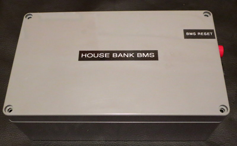
For the BMS on this bank I chose to use the simple and cost effective House Power BMS (HPBMS). EDIT: Clean Power Auto has closed it’s doors.

If you are still looking to build your own a good & reputable BMS manufacturer is the REC BMS. For a simple 12V bank a REC ABMS is the one to get.
Cell Matching
Everything discussed in this article, pertaining to a DIY build, assumes you are starting with well matched cells for:
- Ah Capacity – We like to see them below a 1% Ah Capacity variance but preferably 0.5%
- Internal Resistance – If the cells don’t match well here balance issues will be a problem
Any discussion about balancing the cells would be incomplete without discussing matching the cells for internal resistance and Ah capacity. When I got these cells there was less than a 0.32 Ah difference between the worst cell and the best cell. These cells were made in 2009 and were matched at the factory before being shipped to Balqon. Finding well matched cells today can actually be rather difficult. Over the last 11 years things seem to have gotten worse with LFP cell matching, not better. One probable reason is the plethora of “B” grade or reject grade cells being sold to unsuspecting buyers. It is not uncommon for a customer to show up here at the shop with cells that are missing a logo, branding, serial numbers and or model numbers orthat have a fake QR code.
If you don’t build your pack from well matched cells there’s not a lot that can be done to keep them in balance when working into the knees. This is especially true when using FET BMS products that have minuscule balance currentIf you don’t have a way to confirm the Ah capacity of each cell, you’re essentially shooting darts blind trying to build your own pack.
A LiFePo4 Build Needs to Begin With Well Matched Cells
When you build a pack yourself you will need to confirm cell to cell capacities on your own. The larger the cells the tougher it will be for the bms to keep them in balance especially if they are not well matched..
POORLY MATCHED CELLS
Cell Balancing
Cell balancing is an extremely important aspect of DIY LFP banks. When you have lead acid batteries in series they can be purposely over charged/equalized to a 15.5V pack voltage and they will, in a sense, self balance. With LFP banks this will not happen due to the knee ranges. As a cell becomes full the voltage all of a sudden skyrockets and the cells need to be in balance in order to charge and discharge at matched voltages.
TOP BALANCE vs. BOTTOM BALANCE:
There is much controversy over top vs. bottom balance mostly due to confusion over differing uses.
BOTTOM BALANCE:
A bottom balance simply means the cells are balanced at the lowest “safe” voltage and all cells will converge and match exactly at say 2.75 VPC. In the EV world bottom balancing is almost always the preferred method, and makes the most sense. With high loads, and frequent opportunities to completely drain the bank, a bottom balance is critical with an EV pack. In an EV the car is then brought back to the garage and charged with ONE charge source.
Bottom Balance:
1-Discharge cell using a 20-30A load to 2.50V
2-Let the cell rest at room temp for 24 hours and allow voltage to rebound
3-The cell will now be resting somewhere between 2.75V and 2.85V
4-Apply the load and stop discharging at exactly 2.65V
5-Allow voltage to recover for about 6 hours
6-Repeat load discharge to 2.65V until the resting stable voltage of each and every cell is 2.75V
7-As you get closer and closer to resting voltage of 2.750V a small resistor can be used as opposed to the large load.
Once all cells rest at 2.750V and stay there the cells are bottom balanced.
NOTE: A guy recently dropped off 4 cells he was having trouble “balancing”. He was attempting a bottom balance and intending on using these for fractional “C” use stopping at 70% DOD.. He had spent countless hours trying to bottom balance these cells, and he did.
So what’s the problem?
The problem is that at a 14.0V pack voltage he had one cell at 3.65V and one cell still at 3.380V! His cells tested at widely varying capacities and thus the cell with the lowest capacity was firing into the upper knee sooner than the rest, even at a pack charge voltage of 14.0V. These were cells with an absolute maximum rated cell voltage of 3.600V. With a bottom balance and used cells (I don’t suggest buying used cells) he was sending one cell into the dangerous upper knee even at just a 14.0V charge rate. We conducted a top balance for him and the cells now all remain well balanced at the upper charging voltage range. On the low end one cell will still fall off the cliff early, but at 70% DOD that does not happen.
Misunderstandings are common:
The other issue this owner had was simply one of misunderstanding. He had purchased a Chinese balancing BMS and it balances at the “top of charge”. By bottom balancing his pack he crated more work for the BMS and the BMS was physically undoing his tedious and time consuming bottom balance.
TOP BALANCING:
On boats we have multiple charge sources, shore charger, alternator, solar, wind, hydro or even hydrogen fuel cells. Our risk of cell imbalance is more pronounced at the top end rather than the bottom end. We run a much higher risk of over charging imbalanced cells than we do by over discharging, like the electric vehicle (EV) guys do, but it can still be a risk.
COMMERCIALLY AVAILABLE BMS’s TOP BALANCE
For off-grid / marine use top balancing is the preferred method so the cells converge or are in excellent balance at the top, when fully charged, rather than when dead or fully discharged. It should be noted that any balancing BMS you’ll find works by balancing all cells at the top of charge. In other words, they top-balance. By bottom balancing you just make more work for the BMS.
Your BMS should always protect the cells at the bottom or the top end but, keeping the cells well balanced, ensures an extra level of protection, just as keeping charging voltages out of the upper knee range does. If you don’t discharge below 80% DOD, the cells are well matched, and you have a max charge voltage of 3.5VPC -3.55VPC/ 14.0V-14.2V for a 12V bank, your cells will be very happy. If the cells were not well matched then you will have no choice but to push into the upper-knee at the top of each charge to keep the cells balanced.
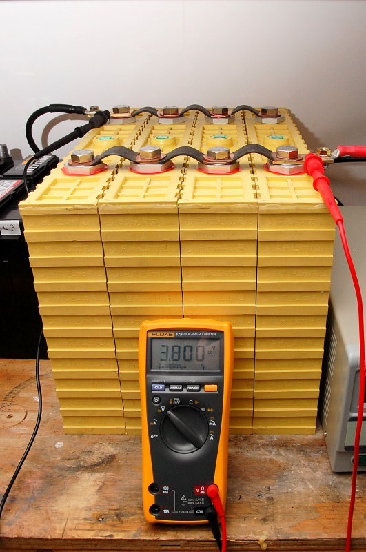
PHOTO: In the photo the four Winston cells have been individually & very carefully charged to 3.75VPC with the bench top power supply shown. The cells were then wired in parallel and allowed to sit for multiple days but weeks or months is even better, if you have the time…
TIP: When ordering cells always order extra cell jumpers so that you can wire the cells in parallel and top balance if you choose to do so.
Balancing – Wire The Cells In Parallel
2010:
As mentioned, I first charged these cells, INDIVIDUALLY, to 3.75VPC and a10.0A current taper. The bench-top power supply allows you to set the voltage to 3.XX and let the cell become “full” at 3.XX VPC. For these cells, based on the data available at the time, late 2010, I held the voltage at 3.75V and allowed the current to tail off to 10A then stopped charging and moved onto the next cell.
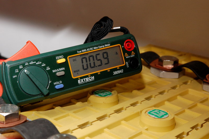
Within seconds of wiring these in parallel only 0.59A was moving between cells which means the balance to 3.75VPC was pretty close.. Leaving them in parallel will get them in closer balance but this can take lots & lots of time.
Updated Cell Balance Process:
Parallel Step-Method Top Balance
My goal when balancing cells is always the following:
Keep the cells in the upper-knee for the shortest amount of time and still net a perfect balance
Trough testing and experimenting with numerous balancing processes I’ve found the “parallel step-method top balance” (PSMTB) has proven to be the absolute fastest method that also keeps the cells in the upper-knee the shortest. This means less upper-knee time for the cells. You will need a variable power supply capable of low voltage (3.6V) to do this. You will also want a model with the highest amperage you can source. Keep in mind that when we wire the cells in parallel the bank capacity grows tremendously. Four 400Ah cells become a 1600Ah 3.2V pack! Getting to 3.40V will take quite some time! The key with the PSMTB come from the fact that the cells are essentially full when you get to 3.40V and 0A. This 3.40V threshold is a perfectly safe voltage for the cells so no matter how long it takes to get there will not be causing damage to the cells. Once at 3.40V this means our steps to get to 3.5oV and then 3.60V are much, much shorter than the first step getting to 3.40V. The step to 3.50V is longer than the final step to 3.60V, which happens pretty quickly.
Parallel Step-Method Top Balance:
1- Wire the cells in parallel
2- Set the power supply to 3.400V and 80% or less of the rated amperage (80% to not burn it out)
3- Turn on power supply and charge cells to 3.400V
4- When current has dropped to 0.0A at 3.400V turn off the power supply & set it to 3.500V
5- Turn on power supply and charge cells to 3.500V
6- When current has dropped to 0.0A at 3.500V turn off the power supply & set to 3.600V
7- Allow current to drop to 0.0A (or very close) at 3.60V
8- Done, pack is balanced.
WARNING: Top each cell up, to a similar SoC level, prior to wiring them in parallel.
Balancing Via Parallel Resting Voltages?
Many often assume that by simply wiring the cells in parallel they will magically get themselves in balance. This is not entirely true, if you expect it to happen in a timely manner. When cells are wired in parallel, the the cell voltages attain a parity voltage rather quickly. Once a parity voltage is attained the transfer or movement of current between cells, in order to balance SoC, slows to a crawl. Ohms law is in control here and we are talking 0.0001A level movements of current. Attaining a true balancing, by letting cells sit in parallel, at a resting non-charging voltage, takes a very long time. You can let them sit for a week or more, but again, this may not be enough time. Balancing ideally requires a voltage differential to move current between or into the cells. When cells are at the same voltage this transfer of current = slow.
You can drastically speed the process by presenting the parallel wired cells with a charging voltage.. The PSMTB method is the fasted way we know of to attain a perfect balance. Once all cells are at the same voltage and no more current can flow into the cells they are all at the identical SoC.
TIP: Never trust the volt meter on the bench top power supply as there will be voltage drop or inaccuracies between the supply & actual battery terminals. Always try to measure the actual battery terminal voltage, using an accurate DVM, when top balancing.
Once you Set the Voltage, Don’t touch it!!
Please don’t adjust your power supply voltage while it is under load. Again, this is because because there will be voltage drop between the batteries and power supply. Unlike the much more expensive BK Precison supplies we use here in our shop, the Mastech power supplies do not have a voltage sense circuit. While inexpensive they are certainly a bit less than full featured. Always pre-set your power supply voltage into a zero amp load and do so based on your DVM’s accuracy not the power supply screen. Once voltage has been set you can then connect the load.
IMPORTANT: Please note that Winston recommended the 3.8V top balance voltage back in 2010. Today we don’t go anywhere close to this. There’s no need to.
Current Moving Very Slowly
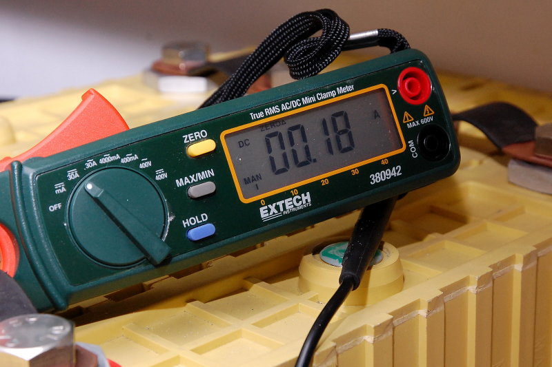
The current moving between cells dropped from 0.59A to 0.18A in a matter of seconds. It kept dropping very, very rapidly. This image and the previous one illustrates how parity voltages mean very little current movement. Within about 20 seconds the current moving between cells was below the resolution for this expensive clamp meter to read accurately. Was “balancing done” at this point, heck no…
Balancing Parallel Cells To 3.800 VPC
IMPORTANT: This was 2010 and today we do not recommend top balancing to 3.800VPC as it is simply not necessary to push the cells to this level.
Top balancing, even at 3.600VPC needs to be closely monitored. Like equalizing flooded batteries you simply do not want to leave them unattended at these voltages for long periods of time. Once the cells hit 3.600V and current has gone to 0.0A you’re done and have a perfect top balance.
EXPERIMENT:
I recently conducted an experiment on some test bench EVE 280Ah cells that paired a “FET balancing BMS“(OVERKILL SOLAR) against a 3.65V parallel top balance to 0.00A. A parallel top balancing to 3.65V & 0.00A actually re-balanced the cells in just under 3 hours.
Using A “balancing FET BMS“(JBD/OVERKILL), after more than 7 hours at shunting / balancing voltages, the cells were still not “balanced“. The point of this was to see what it would actually take, in voltage held at high levels, to actually re-balance a pack. Breaking the pack down and performing a parallel top balance is significantly faster and meant considerably less time for the cells at a high voltage.
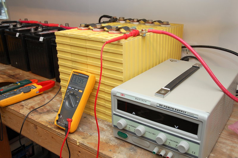
Bench Top Power Supply
As I mentioned earlier I am a believer that if venturing into DIY LiFePO4 it should be done as a system. Part of that system should include funds for a bench top power supply and other equipment to test for capacity etc.. In my opinion a bench top power supply with variable voltage and current should be a pre-requisite for DIY LFP. Can you make do without? Sure, and I am certain Bode Miller could ski with only one leg, but why..? In the whole scheme of things they are inexpensive and they have multiple uses not just for charging or top balancing LFP.Our friends at Current Connected have an excellent one for not a lot of money.
BUY 10A BENCH-TOP POWER SUPPLY
We no longer use the Power supplies pictured. Both our 30A and our 50A models died, and Mastech would not stand behind the product.
In the shop todaywe use our BK Precision Model 1902 B’s. The BK Precision 19002 B is a 1-16V, 60A variable power supply with dedicated voltage sensing leads. The voltage sense leads, to me, are really the driving factor as you get far more accurate voltage at the terminals without worrying about voltage drop through the cables & terminals. It is a very nice piece of gear but they run close to $600.00 each.
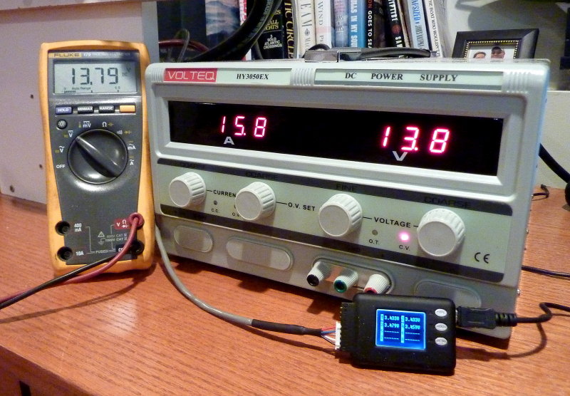
Knobs and Displays:
Left Digital Display = Current Output
Right Digital Display = Voltage
Red Light = Constant Voltage Mode (power supply is limiting voltage to 13.8V)
Left Knob = Current Control Dial
Second From left Knob = Over Voltage Limit
Third From Left Knob = Constant Voltage Fine Tune Adjustment
Right Knob = Constant Voltage Coarse Tune Adjustment
As you can see in this picture with 15A of current flowing the Mastech and the Fluke are in close agreement but I still trust my Fluke a lot more than the voltage display on the power supply.
TIP: When charging LFP cells or banks with an inexpensive bench top power supply please dial the current back by about 20%. This will allow the power supply to run almost indefinitely and not cause undue wear and tear on the unit. We ran my 30A model at 24A and Our 50A model at 40A… I wouldsometimes parallel them and charge at 64A when doing cycle testing.
Nothing makes top balancing easier than a bench top power supply:
WARNING:
If your power supply lacks dedicated voltage sensing, You MUST set the voltage into zero load BEFORE you connect it to the battery! Once connected to the battery adjusting the voltage can lead you to a pile of ruined cells.
Human Error Over Charge!
This cell, and three others, were over-charged by one of the brightest guys in DIY LFP banks. He is also an electrical engineer. $hit happens and I use the $ for an S for a reason.

Quote:
“Charging 4 x 90Ah cells in parallel with a 40 amp 12v charger, thought I’d turned the charger off, didn’t discover it till a few hrs later. The cell was at 4.55v from memory and so hot the terminal bolts burn into the finger tips. The strange smell of the electrolyte vapor, but no sign of any white cloud. The heat was similar to standing in front of an oil heater on full and was still quite noticeable the following morning. Only the 2 cells in the center bulged and they are the only two that failed. The cells at either end had better cooling, they bulged a bit, but they are still part of my battery bank 12 moths later.“
Let’s see how easy these mistakes can happen..
♦These cells were in parallel which means a 3.2V nominal pack
♦A 12V charger was used instead of a power supply or charger capable of LIMITING the voltage to 3.XX
♦He thought he turned the charger off. This is a prime example of HEF (human error factor). No matter how smart we are, we are still capable of making human errors or being forgetful. This is just normal human nature.
♦Cells hit 4.55VPC!
♦Cells DID NOT EXPLODE, Catch fire or do anything other than get very hot!
♦The cells did not even smoke!
♦Two of the four cells actually survived this abuse!
♦Simply AMAZING!!!
Imagine how long your cells will live if you don’t allow HEF into the equation and you charge them safely for a fractional “C” system?
If an EE, and guy who knows more than just about anyone I know on LFP, & the subject of fractional “C” use can do this, you could too. I will mention it again, use a BMS on your bank for HVC / LVC and a bench top power supply for top balancing…
What actually happens if I do over charge?
Over charging forces lithium oxide to form on the cathode. The LFP cathode is, well, lithium iron phosphate. By causing an over charge you have now converted some of the lithium iron phosphate to Lithium oxide and this is not good. There is no reconversion or fixing this situation and the cell is now irreversibly damaged and capacity has been diminished. Even slight over charging episodes can cause increases in internal resistance and cause a loss of capacity.
With the lead acid intended constant current>constant voltage (CC>CV) charging we use in the marine market, and multiple sources of it, your best and safest bet is to limit the constant voltage stage of charging to 13.8V/3.45VPC to 14.2V/3.55VPC rather than the 3.6V to 3.65V some manufacturers spec.
TIP: LFP Cells can be charged to 100% SOC at a voltage of just 3.45VPC or 13.8V. Why push into the upper knee when you don’t need to?
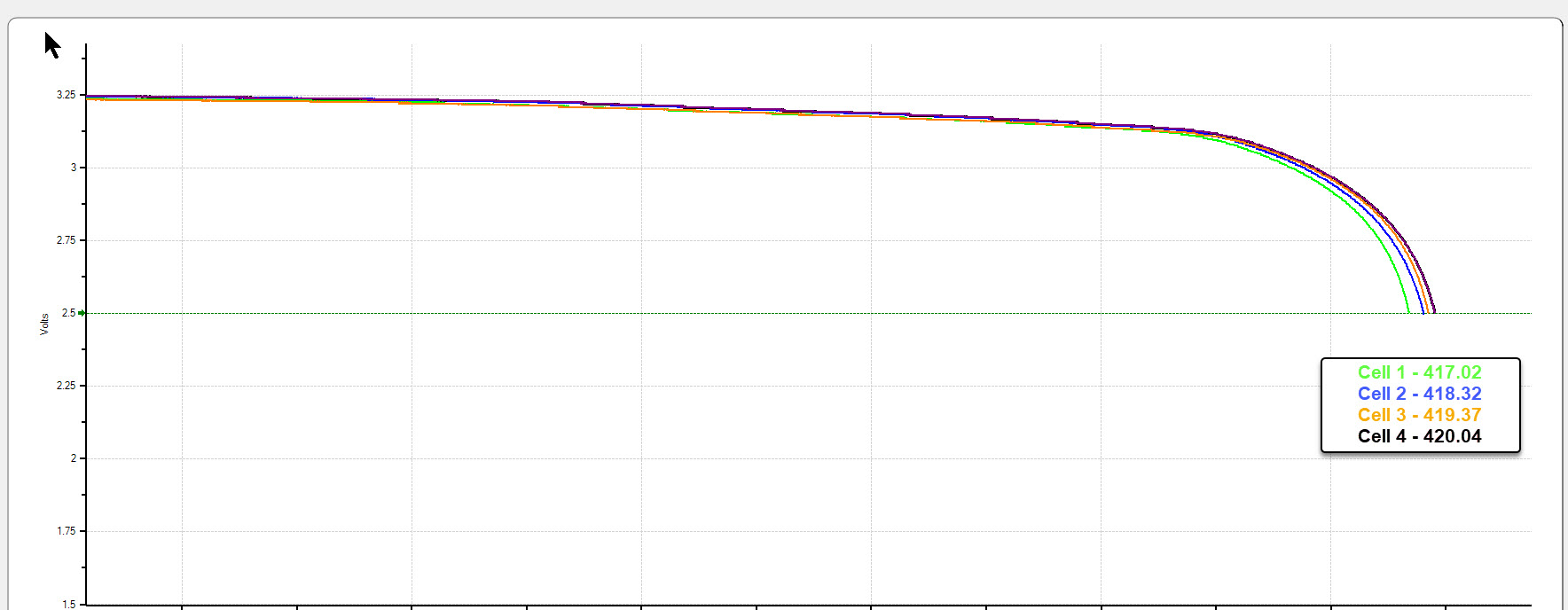
I charge the 400Ah Winston pack featured in this article to 13.8V and a 10A tail current and it still delivers in excess of 400Ah’s in capacity testing.
Image Courtesy: Terry©
No Absorption Time at 3.65VPC
No matter how much I try to explain the confusion between the what the Chinese mean in their manuals, and the reality, folks still don’t seem to believe or trust what I have to say about safely charging LiFePO4, for optimal cycle life, with typical lead acid charging equipment.
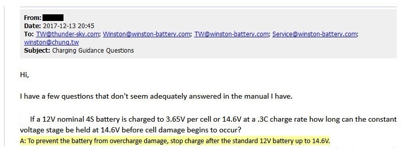
Question to Winston Battery:
Q: If a 12V nominal 4S battery is charged to 3.65V per cell or 14.6V at a .3C charge rate how long can the constant voltage stage be held at 14.6V before cell damage begins to occur?
Answer from Winston Battery:
A: To prevent the battery from over charge damage, stop charge after the standard 12V battery is up to 14.6V.
Despite what far too many LFP buyers want to believe about using lead acid chargers with LFP batteries, and charging technology that features a constant voltage absorption stage, there should be no absorption duration if you charge to 14.6V or 3.65VPC. In other words if you want to drop LFP cells into a lead acid charging environment you do not want absorb the battery, and especially not at 3.65VPC / 14.6V. The confusion is not in the maximum 3.65VPC specification the confusion lies in how the charger operates compared with how the Chinese expect it to operate.
Of course you also need to keep in mind that many balancing BMS’s don’t begin to balance until 3.6VPC. This means you’ll need to “absorb” for 20-30 minutes +/- if the cells are out of balance.
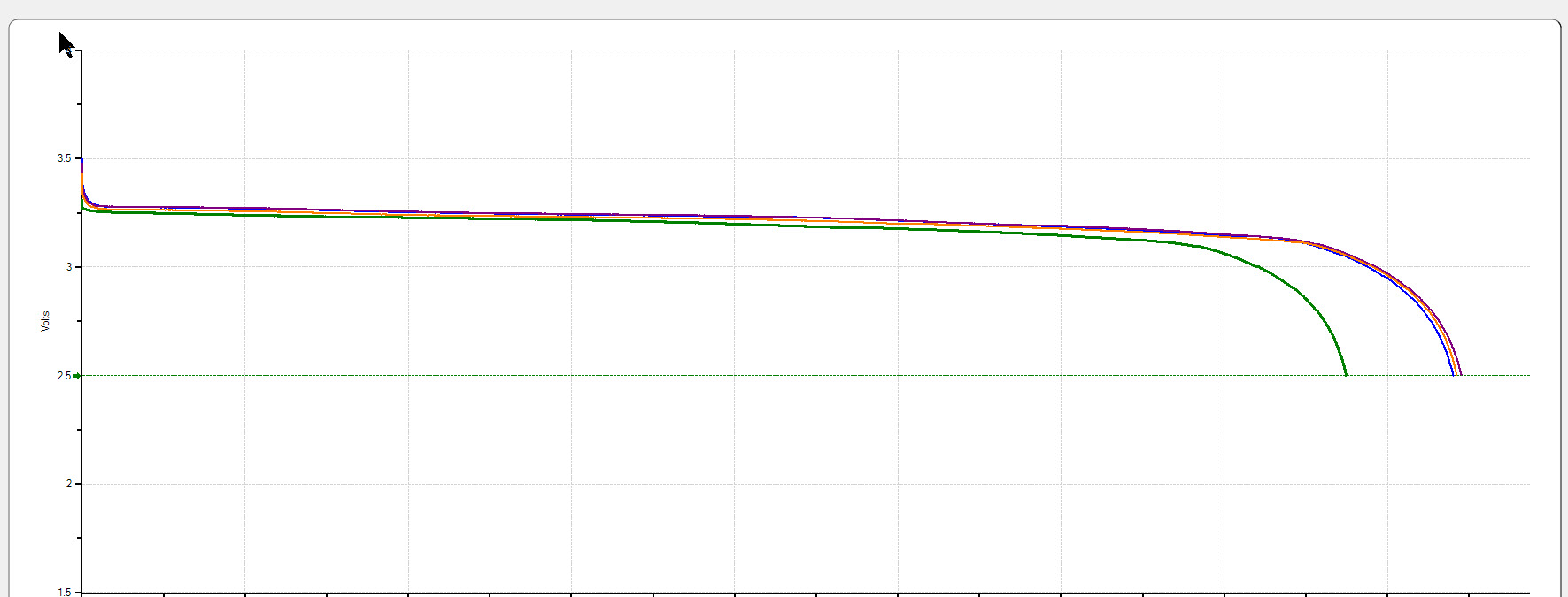
The graph below is from a University white paper where they did some rather abusive endurance testing. They charged Winston Prismatic cells to 3.8VPC – 4.0VPC and then immediately discharged them to 2.9VPC or 0% SOC. The cells survived for 950 cycles before reaching end of life as defined in the study.
“Wow RC it seems 4.0V or 16V for a 12V nominal pack is safe?”
Yes, for some cells it is, if done safely and correctly. This type of outcome can absolutely happen in a lab but it can’t be well translated to a boat using multiple charge sources, all at varying charge rates many of them using “absorption timers“. As I have mentioned before the peak safe voltages are just that “peaks”. As can be seen below the cells charged to just a hair over 3.8V then were immediately discharged. A “peak” very short term duration at this voltage before a turnaround right into a high rate discharge is how this lab test was done.
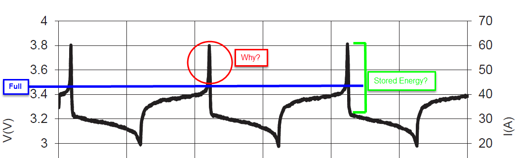
What can be seen in this graph is high voltage knee. The area above the blue line, or about 3.45VPC, becomes vertical. This means the cell is full and no more energy is being stored. On the flip side the discharge down to about 3.27VPC is also vertical and also indicates there is really no usable capacity above about 3.27V. The green ] highlight is illustrating the area between 3.8VPC and about 3.27VPC where there is virtually no stored energy. The red circle is exactly what it is asking? Why would you push your cells into this area, when there is no benefit, no quantifiable capacity to go after, and only the potential for harm if you are not operating in a laboratory setting?
Read the Data, If You Can Find it…
This image includes some very critical and important bullet points copied word for word from a “Drop-In Battery” charge guidance document. A document the reader who sent it to me received only AFTER purchasing the batteries.
Upon perusing their glossy web site, which, marketing wise, suggests these batteries can be dropped into any situation or application, we could not find the charge guidance anywhere. I have removed the brand from the wording in the image as my point here is not to attack the brand but to point out that you may not be getting all the facts on a manufacturers web site and to please, DO YOUR HOMEWORK.
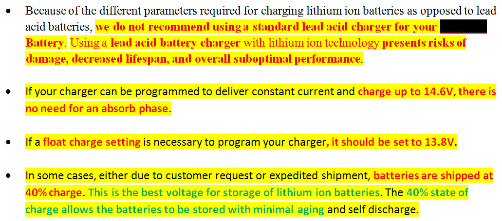
Here are the important bullet points from their charge guidance:
• “Because of the different parameters required for charging lithium ion batteries as opposed to lead acid batteries, we do not recommend using a standard lead acid charger for your XXXXXX Battery. Using a lead acid battery charger with lithium ion technology presents risks of damage, decreased lifespan, and overall suboptimal performance.
• If your charger can be programmed to deliver constant current and charge up to 14.6V, there is no need for an absorb phase.
• If a float charge setting is necessary to program your charger, it should be set to 13.8V.
• In some cases, either due to customer request or expedited shipment, batteries are shipped at 40% charge. This is the best voltage for storage of lithium ion batteries. The 40% state of charge allows the batteries to be stored with minimal aging and self discharge.”
Wow, pretty interesting to say the least. In regards to floating, let’s examine the above statements.
#1 The manufacturer wants to see LFP batteries stored at a resting voltage that represents 40% SOC and they consider this the “best voltage for storage” for “minimal aging“. I agree 100% with storage between 40% SOC and about 60% SOC, in a cool environment (they fail to mention that), and so do many cell manufacturers.
#2 They then go on to suggest setting a float voltage at 13.8V. Huh? This is utterly contradictory to everything they just said above it. “Floating” at 13.8V or 3.45VPC results in the battery being held at slightly above the 100% SOC point. 3.40VPC or 13.6V for a 12V nominal pack would be more appropriate than holding 13.8V indefinitely.
#3 After stating that lead acid charger technology “presents risk of damage“, “decreased lifespan” and “overall suboptimal performance” they go on to tell you how to program a 13.8V float? Float is a lead acid charger feature. LiFePo4 batteries do not need float charging and can only suffer negatively from this practice. There is no positive benefit to LiFePO4 cells from floating at 13.8V/3.45VPC.
EDIT: The manufacturer of this document has finally added charge guidance to their web site. When the reader who sent this to me got his batteries this info did not exist on the web site. Neither he nor I could find it anywhere. What he thought was going to be an inexpensive LFP investment turned into multiple thousands in additional cost to “properly” charge his batteries to the manufacturers suggested guidance. “Drop-In“? Hardly….
More importantly, this manufacturer is now recommending a max charge voltage, for a 12V bank, of 14.0V for batteries charged in series or parallel unless each battery has it’s own charge source. This is good news and it seems some LFP makers are indeed starting to get it.
Choose A Location For The New Bank
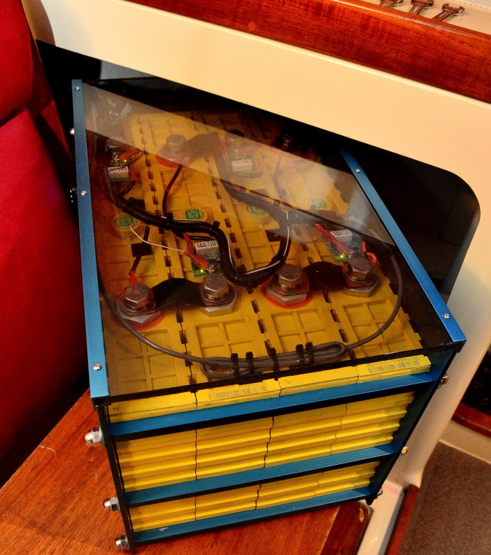
The nice thing about LFP banks is their weight and size are both smaller and lighter than a comparable lead acid bank. Due to these differences in weight and size I was able to relocate the entire bank to a nice dry and higher area of the vessel. I reconfigured a storage area to take the battery bank and it fit like a glove.
Take the time to reconsider where your bank will be and don’t just place it where the lead acid batteries were. There may be better locations than where the lead bank was.. Aluminum cased prismatic cells are even more compact that the plastic cased version above.
Consider the following when choosing a location for a new LFP bank:
♦Weight Distribution
♦Moisture & Humidity
♦Corrosion Potential
♦Not In An Engine Space
♦Heat and Cold Potential
♦Access
The Banks New Home
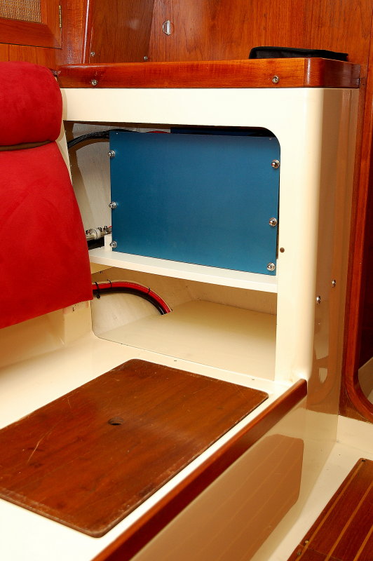
As can be seen the area chosen is high, dry and has good protection for the battery. Don’t be afraid to get creative in where you install the bank, but do be safe..
The Battery Compartment
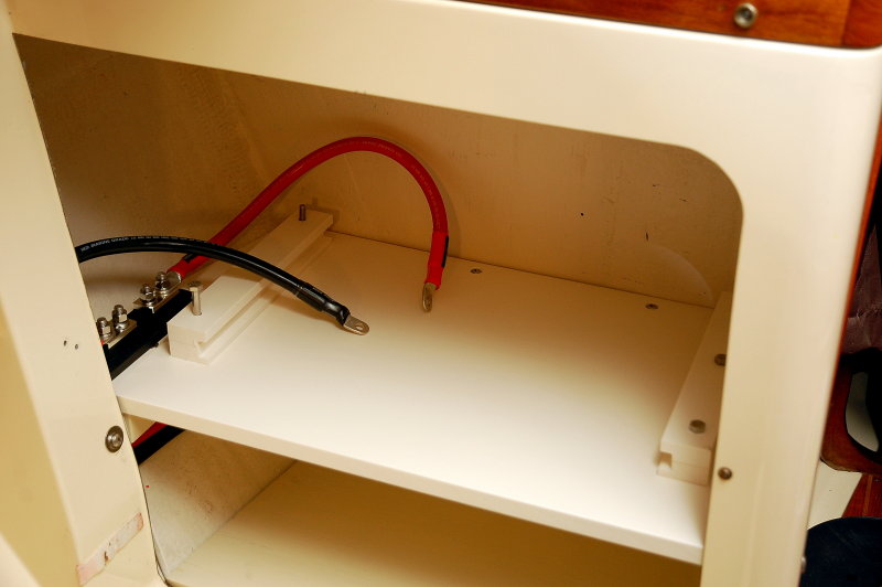
Here’s a shot of the empty battery compartment, simple, clean and with hold down clamps that do not allow for any movement of the installed battery. These banks have the ability to throw massive amounts of current into a dead short so where and how the battery is mounted is an important aspect of the installation.
Make Sure The Battery is Mounted Securely
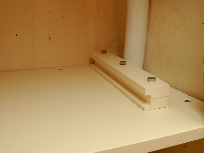
This clamp mechanism uses 3 X 3/8″ bolts and two pieces of 3/4″ thick HDPE board to clamp around the battery cases bottom draw bar. A slot was routed into each clamp at the perfect height to fit the battery case.
The battery case draw bars fit into the notches in the battery cells and compress the cells with 5/16″ SS threaded rod. The square aluminum stock is 1/2″ aluminum square tube which locks the cells in place and fits this hold down clamping mechanism. The battery cannot move at all when installed.
Over-Current Protection
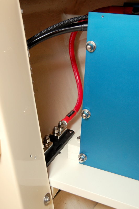
In this photo we can see the battery bank and the red 2/0 wire feeding the Class-T fuse holder. At a bare minimum you want to be using Class-T fuses as your main bank protection for an LFP bank.
This bank can easily throw 20,000A or more of current into a dead short and can damage and literally blow windows out of ANL fuses. I had this happen during the testing of some ANL fuses sent to me by a DIY LFP guy from Cruisers Forum, Thanks Bob E.. Class-T fuses are fully metal encased and are a very safe fuse.
All fuses have what is called an AIC rating or amperage interrupt capacity rating. This is the rating at which the fuse will fail safely. Class-T Fuses have the highest AIC rating of any fuse we use in the marine environment. There are fuses out there with higher AIC ratings but none of them have fuse holders avaible that are suitable for a marine application.
Ideally the main bank over current protection needs to be within 7″ of the battery bank but as we can see here that is often impossible. D’oh!!! There is technically more than 7″ of wire to get from the + battery post to the Class-T fuse here. Is this an unsafe installation, hell no, but sometimes the standards are a little to broad brushed to apply realistically to the real world so we do the best we can.
Unsafe ANL Fuse Failure

During the course of our testing & experimentation with LFP battery banks I blew approximately $400.00 worth of MRBF, ANL and Class-T fuses.
The only unsafe failures we had were off-brand el-cheapo car stereo type ANL fuses. As can be seen here the windows literally exploded out of the fuse when it tripped. I did not have a single unsafe failure of a Cooper Bussmann/Blue Sea Ignition Protected ANL fuse but I only blew about 10 of them. I suppose if you blew 100 you may have an unsafe failure on an LFP bank..
Still, I would strongly urge Class-T as the bare minimum for LFP bank main over-current protection.
NOTE: Class T fuses do not have an ignition protection rating. As near as I can tell, from speaking with Blue Sea Systems, as well as Cooper Bussmann, they have not been specifically tested for this. This only means that they’ve not been tested, not that they would necessarily be unsafe.
Remember an ANL IP rated fuse has an AIC of 6000A and a Class-T non IP fuse has a 20,000A interrupt rating.. If you have a gasoline powered vessel, which requires ignition protected devices, consider this when engineering the over current protection for your LFP system..
Alternator Considerations for LiFePO4
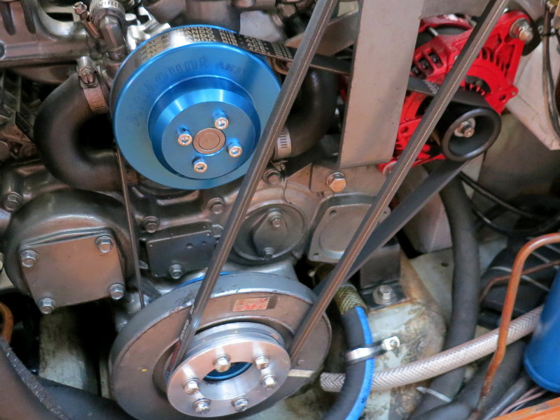
If you decide on LFP, it is best designed and installed as a system. A good system design will almost always include an alternator installation that is suitably designed for that part of the charging system.
Due to the extremely low internal resistance of LFP batteries, and the extremely flat voltage curve, LFP banks can easily tax an alternator to death, if not properly installed. The high acceptance rate of LFP batteries will force the alternator to be in BULK charge mode for the vast majority of the charge cycle, (depends upon amperage/size) before even attaining absorption voltage.
With a high current alternator on lead acid, you can hit limiting/absorption voltage as low as 50% SOC where the alternator begins to catch a break. Alternators for lead acid batteries don’t always need the same level of protectiong from burning out than do alternators charging LiFePO4. With LFP your alternator simply won’t catch a break.
If you cycle the LFP bank to 80% DOD this means you are in BULK charge mode for approx 75% or more of the capacity of the entire bank bank before any sort of voltage limiting even begins.
BULK CHARGE:
This means the alternator has not brought the terminal voltage of the battery bank up to ABSORPTION or the limiting voltage. In BULK the alternator is working flat out, as hard as it can in what is referred to as BULK or CC. (CC = constant current). Once the bank comes up to ABSORPTION VOLTAGE we switch to ABSORPTION or CV (CV = constant voltage). In absorption/CV is where voltage is held steady and current begins to taper off based on what the battery can accept at that SOC and voltage. This is where the alternator finally catches a break but with LFP this duration is very short and only at teh very top of charge.
In BULK / CC the alternators capacity/ability is your limit.
In ABSORPTION / CV the battery determines how much current can flow at a specific SOC and terminal voltage.
Take a 400Ah LFP bank at 80% DOD, that means 320Ah that need to go back in. With a 130A rated alternator running hot, at about 100A, this means BULK charging will be about three hours long. There is no *small-case alternator on the planet I know of or have tested that can run at full bore for three straight hours, into an LFP bank, inside the typical engine room on a boat. *Unless the rectifier has been mounted externally with its own cooling fan.
Let’s assume you’re a marathon runner, and you can do the 26 miles at a pretty good jog. This is similar to a high capacity alternator feeding a large lead acid bank. You start out strong (BULK/CC) but as the race goes on you plateau & settle in at a sustainable pace (ABSORPTION/CV).
An alternator feeding an LFP bank is like trying to SPRINT the entire 26 mile marathon. Not going to happen….
FACTORY ALTERNATORS
Some factory alternators have a built in temp compensator and it resides in the voltage regulator circuitry to reduce current / voltage as the alternator heats up. This really defeats the purpose of “charging fast” or even having an LFP bank if you want to capitalize on the fast & efficient charging LFP batteries can offer.
While this alternator temp compensation feature is self protective of the alternator, in theory at least, it is really a very poor regulation choice for an LFP bank. The other conundrum is that the voltages and temp protection features in these internal regulators are based on lead acid voltages, not LFP. With LFP they can literally cut back so much, due to heat, that little to no current can flow into the LFP bank. We have measured Yanmar / Hitachi alternators so hot they have reduced the voltage output to 13.2V. Considering the resting voltage of an LFP bank is higher that, well. This means little to no charging. Discharge the bank deep enough and even these internally temp protected alternators will literally cook themselves. Bottom line? Do it right and include a performance alternator, regulator, temp sensors and pulley kit (for anything over 100A) as part of your “system“..
PHOTO:
Here we are looking at a Yanmar four cylinder engine with a Balmar / Alt Mount serpentine conversion and a Balmar AT series 165A alternator. The Balmar AT series is a hairpin wound small case alternator. This stator / rotor design is relatively new technology for the marine market and allows extremely high performance out of a small case alternator, but remember this is still a small case alternator and is not “constant duty rated”. Into an LFP bank even an alternator like this needs protection.
The Balmar AT series (shown above) was recently replaced with the new Balmar XT series and these are one of the best small case alternators you can buy for LFP. At the moment they are the best suited small frame internally rectified alternator, available for an LFP bank. Unfortunately many sailboats don’t have the room for a massive large frame alternator with external custom brackets etc. If you do, that is great, and I would steer you in that direction every day of the week.
Does this mean other small case high performance alternators can’t be used on LFP? Absolutely not, it just means the percentage of “rated output” you get out of the alt will be less than it is on an XT series and it will need to be dialed back in the regulator settings, for self protection, further than other externally regulated small frame alternators will.
Large Frame J180 Mount Alternator
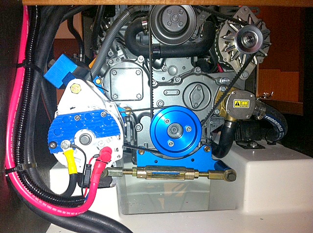
When space allows a large frame extreme duty alternator is always better suited to charging LFP banks. These alternators are purposely designed from the ground up for driving large loads for long periods of time. Small case alternators require more current limiting or external rectification, to survive LFP banks than do large frame alternators.
PHOTO: In this photo we have a large case Balmar J180 mount alternator on a Balmar/AltMount custom bracket driven by a serpentine/rib belt. If you have the room, a large frame alternator is the best option to go with for charging LFP banks..
Image Courtesy: C. Kelley©
Alternator Drive Belts
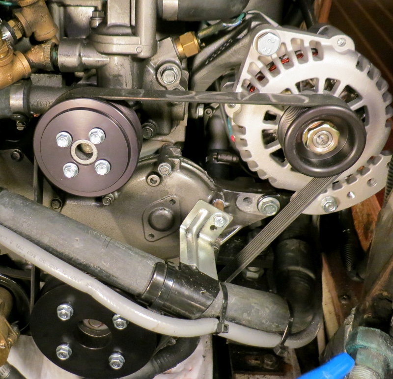
In order to get lots of current out of an alternator it requires a considerable amount of work on the part of an alternator belt. If designing the system for LFP there is no better option than a multi-rib or serpentine belt kit for your alternator. You could also self design a geared PTO system too, but $$$$$…
A single J10 (10 groove) serpentine belt is capable of driving upwards of 250A + with less heat, less belt tension and less strain on water pump or alternator bearings.
TIP: Universal & Westerbeke suggest the largest alternator they want to see on their engines is 190A. Yanmar has no such advisory that we have been able to find. With proper regulation you can run a 225A + alternator current limited to 190A, and do this all day long.
#1 Belt Choice = Serpentine / Multi-Rib – Balmar/AltMount or Mark Grasser DC Solutions
#2 Belt Choice = Dual belt configuration. This is a very distant second choice. Dual belt kits rarely if ever work as intended or share the load equally among belts. On an LFP bank they can become a belt dust nightmare. Matched pairs of belts are also getting extremely tough to find because even industry has moved away from v-belts. You will have belt dust issues with a dual-pulley/belt configuration driving LFP. Unless you already have dual belts, you would be better off to spend your money on a serpentine kit.
#3 Belt Choice = 1/2″ Single V-Belt – A single 1/2″ v-belt, driving an LFP bank should be current-limited to approx 80A of current. The caveat is that you’ll need darn near 180 degrees of belt wrap to drive the 80A with minimal belt dust. If you have less than 180 degrees of belt wrap the current capability will be lower. I do not advise charging LFP with a single v-belt.
#4 Belt Choice = 3/8″ Single V-Belt – A single 3/8″ v-belt driving LFP should be limited to approx 60A of current. The caveat is that you’ll need darn near 180 degrees of belt wrap to drive the 60A with minimal belt dust. If you have less than 180 degrees of belt wrap the current capability will be lower. I do not advise charging LFP with a single v-belt.
NOTE: I am ignoring common wisdom that a single 1/2″ belt can drive 100A and a 3/8″ belt can drive 80A. This is all well and good with lead acid but not for 3-4 hours plus at full bore with LFP. The same goes for large banks of AGM or GEL with a small alternator.
PHOTO: An Balmar serpentine pulley kit and a Mark Grasser DC Solutions Premier Series 140A alternator.
Alternator Voltage Regulation For LiFePO4

A good voltage regulator is critical for an LFP bank. It is my belief that no better regulators currently exists for LFP than the Balmar MC-618 or the Wakespeed WS500. These regulators allow nearly every conceivable parameter to be adjusted from; voltage, to alt temp compensation, bulk, absorption and float duration, thresholds for transitions from bulk to absorption or absorption to float, the ability limit the field current and do “current limiting” of your alternator etc. etc. on and on. The WS500 ups the game a bit with the optional current-controlled regulation in order to stop charging once a voltage and tail current have been attained. Of critical importance in LFP both regulators use a dedicated voltage sensing circuits. Accurate voltage sensing allows the regulator to see an accurate reflection of the battery terminal voltage, provided you wire it correctly.
IMPORTANT VOLTAGE REGULATOR FEATURES:
#1 User Defined Charging Parameters: Adjustable bulk, absorption and float voltages allow you to tailor the regulator to suit LFP banks. Float can be set low enough so that it essentially turns the regulator off when the bank is “full”.
TIP: In order to get the voltage settings low enough for LFP banks with a Balmar regulator one must work backwards in the custom programming menu by starting with float first, then absorption then bulk. This article will help owners understand how to properly program a Balmar regulator:
Programming a Balmar Regulator Article
If you want BULK at 13.9V you need to lower/adjust ABSORPTION to 13.8V first. This is because BULK can’t be lower than ABSORB. There needs to be a minimum of 0.1V between “stages”. I use: BULK = 13.9V, ABSORB = 13.8V, FLOAT/OFF = 13.2V
#2 Dedicated Voltage Sense Circuit: This feature is not to be underestimated on an LFP bank. ACCURATE voltage sensing is of critical importance. The MC-614 + v-sense wire does nothing but sense voltage. The + v-sense wire is used with the regulator B- to create an accurate voltage sensing circuit. On the ARS-5, the next step down, this wire both power the regulator and senses voltage. This can create inaccurate voltage sensing due to the additional current carried on the v-sense/reg B+ wire to power the regulator.
TIP: In order for the v-sense “circuit” to work correctly, and accurately, you must wire the Balmar regulator negative lead directly to the negative post of the battery bank which you are measuring. Regulator B- is the other half of the voltage sense “circuit“.
#3 Current Limiting: Remember when I said there is no small case alternator on the planet that can run at full bore for 3-4 plus hours into an LFP load in boats engine bay..? Well this is where you fix this and help save and extend the life of your alternator.
Balmar calls this BELT LOAD MANAGER. It was formerly called AMP MANAGER, but it works for both belts and saving the life of your alternator. Field potential limiting (Belt Load Manager) allows you to essentially derate the output of your alternator by limiting the maximum field potential to the alternator. The field wire from the regulator is what drives the alternator so, by limiting the capability of the field wires maximum potential you in turn limit how much current the alternator can drive. This is a simple adjustment in the settings menu and should be made when the alternator has been run up to temp.
Every alternator will be slightly different but usually Belt Manager level 3 or 4 is a good place to start. I generally suggest buying an alternator that is larger than where you want the expected hot rated output to be and then dialing it back in Belt Manager..
On my own boat I run a custom built 160A externally rectified small frame alternator. External rectification was the only way to get maximum output from the small case alternator without it over-heating. Before converting it to external rectification it was current limited to about 120A and it still occasionally bounced of the alt temp sensors limit. Belt Load Manger (current limiting) is now set to zero/off…
With external rectification it will now drive at full-bore for hours and rarely break 230F. This is exactly what I want to see. To not exceed 240F, before going to external rectification, I controlled this by limiting its max potential using Balmar’s Belt Load Manager feature. This kept the alternator from melting itself down and prolonged its useful life. In the end I was going to need to be a large frame extreme-duty alternator such as a large frame Balmar or external rectification. Fabricating a custom bracket for a large frame alt was more of a project, time wise, than going externally rectified, so I chose that route instead.
#4 Alternator Temperature Compensation: A regulator that offers an add an on-alternator temp protection sensor is additional insurance so you won’t wind up with an Alternator fire.
Cooked Alternator Stator
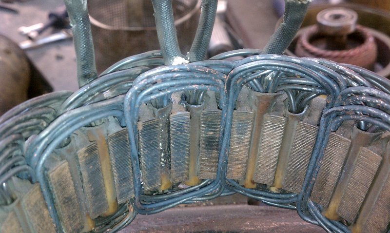
This is exactly what happens when you don’t current limit an alternator that will be feeding a LiFePo4 bank. It will literally cook itself. Here the magnet wire coating has literally been cooked right off the stator windings. This happened on an AGM bank and this was a factory dumb regulated alternator with no built-in thermal compensation. It just ran and ran and ran until it burned itself out.
How can you avoid this? Use a Balmar MC-614 or Wakespeed WS500 regulator, and current limit the alternator, especially if you have an LFP bank!
RPM, Engine Room Temp & Current Limiting:
What does low engine RPM have to do with alternator heat? Many sailors and cruisers want to charge at low RPM while on the hook. Today’s high performance alternators can put out a substantial portion of their total output at just a fast engine idle. This is good, as it keeps your neighbors happier in the anchorage.
But wait, there is a catch, always is.. The problem with low RPM charging is that with a fast idle we have very slow alternator fan speeds. The speed of the rotor actually serves to keep the alternator cool.
Arguably the most abusive loads for a high performance alternator are not at cruise RPM, they are usually at fast idle. Keep in mind many of the new small case alternators can handle 17,000 – 19,000 shaft RPM. This creates excellent cooling but we never get there on most cruising boats. Because of this the alt is best set up and hot-load tested to fast idle RPM. This is where it can get the hottest.
Alternator Set Up & Load Testing:
It is not just good enough to program the regulator and walk away. Every alternator will respond differently to the field wire from the regulator. Proper set up will lead to a long alternator life and an alternator that can survive the abuse an LFP bank throws at it.
“Rod, How do I do this?
It is not difficult. You will need the following:
#1 An on-board inverter capable of exceeding the alternators current capability, usually 2000W or more, or a portable inverter capable of at least 2000W or more.
#2 A good restive AC load such as a heat gun, hair dryer or portable heater. If the alternator and inverter are large enough you may need two of these devices.
#3 A remote temperature sensor attached to the alternator case that can be read with the engine room 100% closed up and sealed tight. Most DVM’s offer a remote temp probe.
Alternator hot load testing and set up:
Step #1 – Connect a DVM temp sensor (Fluke etc.) to the alternator and close engine room
Step #2 – Run the boat under cruising load, with the inverter loaded down via the heater, and at cruise RPM for at least 30 minutes.
Step #3 – Return to dock or mooring and leave the motor running at fast idle
Step #4 – Keep inverter/AC load running. This load should be in excess of alternators capability.
Step #5 – Monitor alternator temp and ensure temp does not exceed 225F?
Step #6 – If it goes over 225F, adjust Balmar Belt Manager to level #1
Step #7 – Continue load testing and monitor temp, did the alt still go over 225F?
Step #8 – If so move to Belt Manager Level #2
Continue this process until the alternator stays below 225F loaded to max output.
TIP: I start at Belt Manager Level #4 and work my way up. Most alts require level #3 or #4.
TIP: Balmar’s Belt Manger used to be called Amp Manger in previous regulators. It is the feature you use to current limit your alternator and prevent it from cooking itself.
Protecting the Alternator from a BMS Disconnect (LOAD DUMP):
One of the biggest obstacles of LFP is protecting charge sources such as alternators and inverter/chargers from a BMS disconnect. If the charge source is pumping out amperage, and the BMS decides to disconnect, the outcome can be fatal to your alternator. On many boats the DC bus is also connected to the charge bus and this means the voltage transient that is caused by the BMS/LFP battery disconnecting, causes a massive voltage transient. This transient can not only blow the rectifier in the alternator but can also destroy expensive navigation equipment.
Ideally your BMS should feature a charge control circuit. Lithionics calls the FCC or (Field Control Circuit). This circuit disables the charge sources well before the battery is actually disconnected. The well before part here is critical as the large magnetic field needs to be de-powered before the load is disconnected. For a Balmar regulator this shutdown should be the Red wire in the regulator harness. Shutting down the brown or ignition wire is not fast enough to protect the alternator from a BMS load dump.
Unfortunately drop-in batteries and most aftermarket BMS systems are designed for electric car use and don’t always have the ability to shut charging down before the BMS open-circuits the battery.
Fortunately Sterling Power now & Balmar make Alternator Protection Devices. It is used to prevent a load dump from causing a massive voltage transient. It is our belief that any system that does not have a way to shut charging down correctly needs, at a bare minimum, an APD.
A BMS can disconnect for the following reasons:
- Cell Over Voltage
- Cell Under Voltage
- Cell Temperature
- BMS Temperature
- BMS Current Limits Exceeded
If there is a bad cell, temperature too high, too much charge current, a glitch in the charging voltage settings or a cell imbalance issue creating an over-voltage condition, the battery will physically disconnect itself from the vessel. Most drop-in LiFePO4 batteries can disconnect themselves with no advanced warning to the vessel occupants. This is called a load disconnect or load dump.
A load disconnect or load dump is something a lead acid battery can’t physically do on its own, so this, by definition makes “drop-in” LFP batteries not so “drop-in” because we now need a ways to ensure our alternator or inverter/charger is not suffering load dumps. Of course you don’t need to take our word for it. This is from Balmar, the worlds largest specialty marine performance alternator and regulator manufacturer.

Sure, many an owner has moved a battery switch with the alternator charging and had the destroyed alternator to show for it but the battery did not do this without warning, and the owner made a simple, and often fatal to the alternator, mistake. If a BMS disconnect / load-dump occurs, when charging with an alternator, or even a large transformer based inverter/charger, the resulting *voltage transient, can damage the charge source and also what ever is connected to the DC bus/system such as sensitive marine electronics.
*Voltage Transient – What occurs when a charge source such as an alternator is suddenly disconnected from the load (battery). The current now has nowhere to go sending the voltage through the roof. When the load (battery) is suddenly disconnected the voltage skyrockets to damaging levels in milliseconds.
During normal operation the alternator operates just fine: (most drop-in batteries have the BMS disconnect on the negative side of the battery)
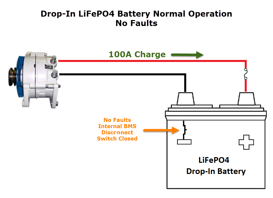
In a fault condition this is what can happen to the alternator:
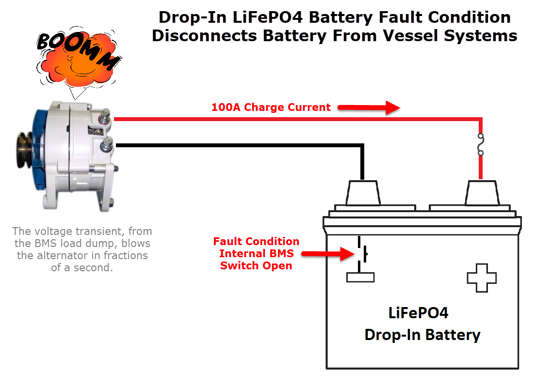 What a Load Dump Can Look Like:
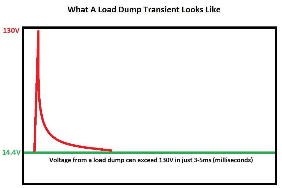
Even if your alternator were to survive a load dump, other items on-board your vessel, connected to the DC load bus, may not survive. This is why we recommend Balmar APM for every vessel that has LFP batteries. The Alternator Protection Module clamps the transient to a safe level. Sterling also makes a similar product but the Balmar is much better built and has no fuse to trip..
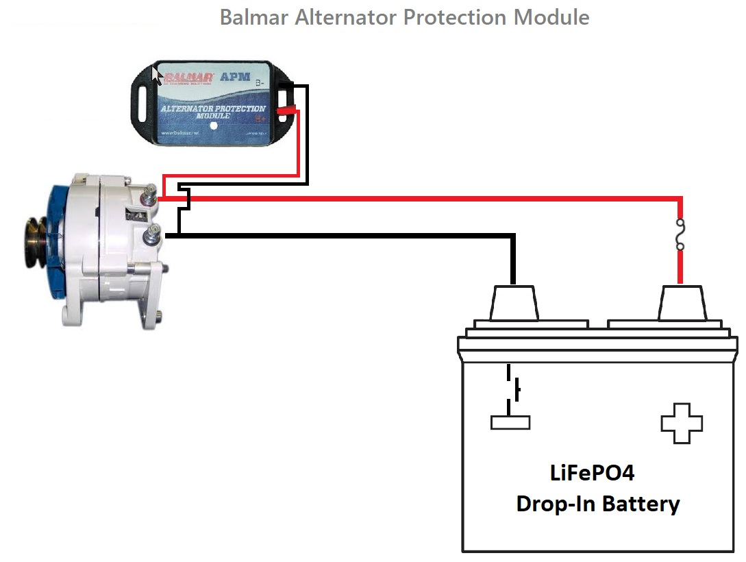
If you’re installing LFP batteries a Sterling Power Alternator Protection device is cheap insurance and a must-have device:
AC Battery Chargers & Inverter Chargers
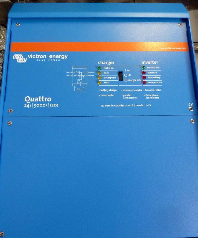
Just like with external regulators we want to be able to control;
Max Current Output – A small generator may not be able to handle a large charger
All Charging Parameters – This is a must for an LFP bank
Dedicated Voltage Sensing – This is a critically important aspect for an LFP design.
High Current Output Capability – This compliments the bank and allows for faster charging. The largest charging capacity commonly found will be in an inverter/chargers (I/C’s) often called combi’s. Stand alone chargers are usually smaller in current output.
NOTE: Most inverter/chargers drop current output as they heat up. Just because it says 130A does not mean it can do this indefinitely. When hot you may see considerably less than “rated” output.
Dedicated Voltage Sensing Rant:
In a nut shell there are very few chargers or inverter/chargers out there that offer dedicated voltage sensing. This is really quite frustrating for those of us working with LFP batteries. Sadly, the charging portion of far too many inverter/chargers is engineered like an after thought. The engineers who fail to provide dedicated voltage sense leads, on battery chargers or inverter/chargers, have failed you, the customer, when you’re seeking fast charging performance.
Let’s Examine a Few Examples of Inverter/Chargers:
Mastervolt – No dedicated voltage sensing
Magnum – No dedicated voltage sensing
Xantrex – No dedicated voltage sensing
Which manufacturers actually care about battery charging performance?
Victron – Victron I/C’s have dedicated voltage sense terminals right on the main unit. Kudos to Victron!!
Outback – Can be done but requires FLEXNET DC & MATE Remote Control.
The engineers at Victron actually understand charging! Of course they also make their own line of LFP batteries. Perhaps their experience with LFP opened their eyes to including dedicated voltage sensing on-board their I/C’s.
No matter how big you size the wire for, with a 130A+ inverter/charger you will still have some voltage drop between the charger and the physical battery terminals. Most charger manuals only account for wiring voltage drop but we should remember that each termination, busbar, shunt, fuse, battery switch etc. results in even more voltage drop. It is not uncommon to see 0.4V -0.8V of drop, at full charging output, even on factory installed inverter/chargers. While the I/C makers often insist you keep the unit 5′ from the batteries, this is not always possible on a boat.
In the real world, voltage drop happens, and is simply a fact of life.
How do we fix that?
Simple, dedicated non current carrying voltage sensing leads connected directly to the battery terminals so the charger can compensate for slight voltage drops in the system wiring and not enter absorption or the voltage limited charging stage prematurely.
Consider that just a 3% voltage drop, something most boat owners feel is perfectly acceptable, winds up creating a .42V drop, at the battery terminals, when the charger is pumping maximum amperage and trying to attain a voltage, of lets say, 14.0V.
If we start with a target voltage of 14.0V, and drop or lose .42V, this means just 13.58V at the battery terminals. Even an LFP bank, which normally operates around 13.2V, can come up to 13.6V well before it should have its current limited by the charge source.
Due to voltage drop the charger simply begins limiting voltage because it thinks the batteries are at 14.0V, but they are not. The charger is thinking it’s in constant voltage mode but it should not be and instead should still be in BULK.. This type of situation literally murders fast charging performance, especially with the narrow voltage range of LFP. This is not just bad on LFP banks but also bad form on large lead acid banks as well. Because LFP has such a narrow voltage window, that it operates within for charging, any charge system voltage drop becomes a much larger issue charge performance wise.
How voltage drop murders charging speed:
At the charger end the charger sees 14.0V and enters CV mode or constant voltage mode. The charger now begins limiting voltage and current by controlling the output of the power supply, so as to not over shoot 14.0V. The problem is at the battery end, the voltage is below 13.6V and only so much current can flow into the battery at 13.6V, even an LFP bank. Voltage is the pressure that allows the charge current to flow into the batteries and LFP banks are not Ohm’s law exempt.
Attain a limiting voltage too early, due to voltage drop, and you have just extended your charging times and will have a longer current taper to get to 100% SOC, just like lead acid!
Dedicated voltage sensing at the battery terminals is critical to FAST CHARGING PERFORMANCE. If you use a generator to power an AC charger proper voltage sensing means less generator run time. If a charger or inverter/charger does not offer you this option please BUY ONE THAT DOES!
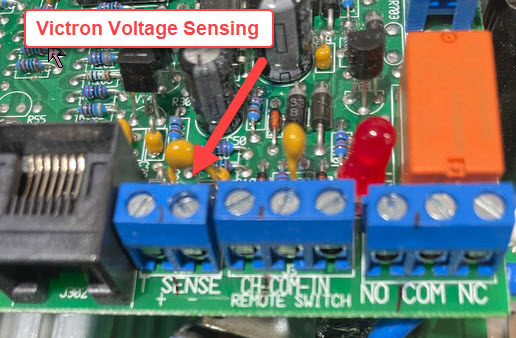
Victron Inverter / Chargers represent an excellent value in an LFP capable inverter/charger, especially one that has dedicated voltage sensing leads. By the time you are done with the Outback, by adding FLEXNET DC (allows for volt sensing) and the MATE (remote control), you are well in excess of the cost of a Victron Multi-Plus Combi. Course if you are in the US the Outback is a US company and supports US jobs.
Choose your AC chargers carefully.
0.4C Charge Rate & 12v 100Ah Winston Pack
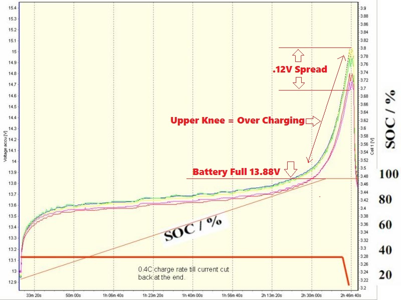
Okay you’ve heard me discuss how to safely charge these batteries when used as house banks at factional “C” usage, and here’s a prime example of what I am talking about.
As we can see in this image the battery has hit full at just 13.88V (pack voltage) with a .4C charge rate. A .4C charge means a 40A charge on a 100Ah battery pack. Anything above this voltage point is technically over charging the battery, because the charging is done. If you stopped at this 13.9V level, and tested this pack for Ah capacity, you would see 99.5% to 100% of the capacity. I know this because I have conducted these tests, in our shops lab, many times.
TIP: Charge rate also plays a role in when your batteries are full. It’s not just voltage.
The over-charge can be seen by the abrupt hockey stick rise in voltage once the cells hit “full”..
CONSIDERATIONS: On a DIY built bank, with impeccably matched cells, the only benefit to charging to voltages above 13.8V – 14.2V at a .3C to .5C charge rate, is a slightly shorter current taper at the top end of charge. On this 400Ah bank I allow the current to drop to 10A at 13.8V with a .35C charge rate before deeming the bank full enough to reset the Ah counter. Stopping the charge at 13.8V and ≤10A nets over 400Ah of capacity from these 400Ah cells.
Maximum Peak Charging Voltage: 14.2V to *14.6V (*No absorption at all – STOP once this voltage is attained)
*If you have drop-in batteries, or cells you don’t know match extremely well, you will want to charge into the BMS’s “balancing range” with each cycle and hold this for the manufacturers specified duration.
Optimal Charging Voltage: 13.8V to 14.2V (*for a DIY built bank with well matched cells)
What Has Industry Learned?
As you push into the upper knee the cells can rapidly run out of balance as one cell becomes more full faster than another. This is why cell matching is critical to any LFP battery build. As cells age Coulombic efficiency can change, especially when over-stressed by using high charge voltages and CC/CV charging equipment. The actual cell to cell capacity can also change as can internal resistance. By staying out of both knee ranges, voltage wise, the cells tend to cycle up and down with very little voltage drift. Regularly pushing into the upper knee often creates a need for more cell balancing and many of the BMS companies pray on this.
If you can get 98% – 99.9% of the capacity out of the bank at a 13.8V – 14.2V maximum charge voltage, why go any higher?
Please Source the Data:
Please, I ask anyone reading this article to present me any credible scientific data that shows why going above13.8V – 14.0V or 3.45VPC to 3.50V per cell is good for the batteries? I would honestly like to hear any solid scientific reason why it is necessary to do this on each cycle? Thus far the only reason I have had, from actual battery researchers, is this: “Most DIY’s simply won’t be starting out with “well matched cells” unless buying from a reputable dealer because they don’t have the test equipment to ensure this.”
I fully accept that argument! This is why I always preface anything having to do with a DIY build with “with well matched cells”…
I have nearly 150 research/white papers in the CMI data-base and not a single one of them gives any good reason to push these cells into the upper knee with regularity. Not a single one.
What do we know about higher voltages and LiFePO4 battery longevity?
#1 Just letting these batteries sit idly at full charge degrades an LFP batteries cycling life. The manufacturers want them stored at mid-range SOC for the longest life.
#2 Research has shown that all Li-Ion batteries are degraded by merely charging “to” a high voltage and stopping. Imaging if they charged “to” that voltage and then “held it” as lead acid charge equipment does? I can’t imagine it is going to be better for them.
#3 None of the LFP battery cycle life claims are tested by holding a constant voltage even for just one minute. They charge to 3.XX then discharge immediately.
Float & Storage Life?
STORAGE SOC EXPERIMENT: We recently ended a very expensive experiment regarding storage at 100% SOC. The test duration wound up being 12 1/2 months using four 100Ah CALB SE cells where they were charged to 100% SOC and then left to sit idle with no connections to a BMS or other parasitic loads. The low temp recorded over the 12 1/2 months was 46°F and the high temp was 87°F. This test was meant to be a representation of the real wold.
A min/max capture thermometer was used to record the peaks. The cells, prior to letting them sit at 100% SOC for 12 1/2 months, were regularly testing at 101.2 to 101.3 Ah’s of capacity (previous 6 Ah capacity tests) as a 12V nominal bank. After 12 1/2 months the cells were discharged to a cut off voltage of 2.9V for the lowest cell. After 12 1/2 months of doing nothing but sitting there, at 100% SOC, the cells had lost 11.6% of their previous rigorously confirmed Ah capacity. Now imagine if you additionally stressed the cells by continually float charging them. Ouch!!!!
“The cells lost 11.6% of their confirmed capacity just sitting at 100% SOC”
UPDATE: We have now completed a second round of this type of testing with a brand new prismatic cell. The difference was rather dramatic and I have no explanation as to why? The second test we did went for 13 months, under identical testing criteria, and this cell only lost 3.8% of previously verified Ah capacity. While this is quite a bit less capacity loss it still lost capacity.
How can LFP cell manufacturers suggest that the mere act of storage, at 100% SOC, is bad for the cells, which we have physically tested and confirmed is degrading them, and then suggest it is okay to float? How can they say “store at 50-60% SOC” yet then give you a “float” voltage?
Image Courtesy: Terry©
LFP Cycle Life
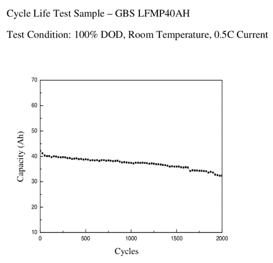
This is one of the few tests I have seen on an LFP battery where they took it to 100% DOD every cycle. The cells were made by GBS and the cycle tests were to 100% depth of discharge or 0% SOC. The tests were conducted at room temperature and the cell was discharged at a .5C load or 20A on a 40Ah cell.
At 2000 cycles, to 100% DOD, these cells were still putting up 35Ah’s or just 5Ah’s shy of the as new capacity rating. Even for lab type test this data is utterly amazing.
I
Image Courtesy: Elite Power Solutions©
Capacity Testing – Create A Baseline
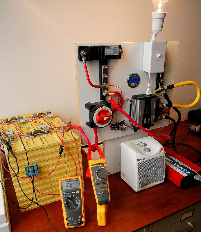
2010: In 2010 this was the very crude capacity tester I created for this bank. Not pin-point accurate, from a scientific stand point, but good enough to note trends and a baseline to start from. Not too long after this we invested in a more serious discharge tester that can actually do a .3C discharge on this bank.
With expensive batteries such as LiFePO4 it’s a wise idea to create a baseline capacity figure that you can repeat at least once per year. For the fist 11 capacity tests on this bank, which I conducted every 50 cycles I used the set up pictured here. For loads I used an inverter and ceramic disc heater plus an incandescent bulb to get the current to approx 100A. This represented a load of approx .25C. To count Ah’s removed from the bank I used a Victron BMV Ah counter.
This set up worked ok, and so long as the cells were tested at the same temp, using the same equipment, the test was fairly repeatable, with some level of accuracy, but not a lot. On the first capacity test after the initial top balance the bank yielded 425 Ah’s at a .25C load when charged to 13.8V and current allowed to taper to 10A.
With this initial capacity test I now had a solid baseline from which to monitor changes over time. I ran a capacity test approx every 50 cycles through 1000 cycles and now it is every 100 cycles. Too much work every 50 cycles, even fora bank used for educational purposes as this one is.
In order to run a capacity test you will need a load plus a way to track Ah’s. You will also need a way to track individual cell voltages and cut the test off when voltage drops on the lowest cell to 2.8V -3.0V where ever you decide.
It is not important to test these cells at a .25C, .5C or 1C rate because the use on a vessel, as a house bank, will draw considerably less than that. Using higher C rates just makes the testing ever so slightly shorter in duration.
There will be some slight differences in capacity between say a .1C and a .25C test, because these cells do have some Peukert-like effect, but this will be nowhere near as pronounced as it is with lead acid batteries.
Do yourself a favor and create a baseline Ah capacity for each of your cells. You can’t just trust the cell manufacturer. Always keep in mind that the lowest capacity cell is determines the capacity of the bank. Do this so you know what you actually have for capacity in each cell. Go a step beyond and set up some tests so you know the internal resistance of each cell too.
It’s kind of tough to program an Ah counter when you really have no idea of the actual capacity other than what the manufacturer tells you. There have been numerous reports of folks not getting the “rated” capacity in their cells, as well as more capacity, and without a baseline you really have no way to know whether you started with less capacity or you caused premature capacity loss, through your treatment or mistreatment of the bank.
Moving Towards Better Accuracy In Capacity Testing
PHOTO: The 400Ah LFP bank, a 60A lab grade power supply for charging, and the 40A lab grade DC electronic load tester. Most of the smaller wires, in this spaghetti mess, are voltage sensing leads.
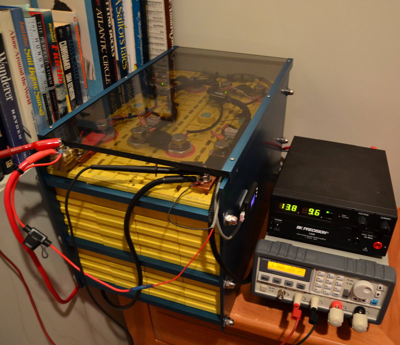
One of the services we offer our customers at Compass Marine Inc. is 20 hour capacity testing for their expensive AGM or GEL batteries. Some even take advantage of it for expensive flooded deep cycle batteries and more recently we have been testing a slew of LFP batteries & cells. The only accurate way to capacity test a lead acid battery, for use as a deep-cycle bank, is to physically capacity test it using BCI industry standard testing procedures. The 20 hour test is most representative of the loads used on boats and thus a true 20 hour capacity test is what we use here in the shop, for lead acid banks.
Many years ago I built an Ah capacity tester using an Ah counter, relays and DC loads but the accuracy was not as good as I would like because the DC load needs to stay steady the entire duration and this means manual manipulation of current during the discharge test. As the voltage decays the current you initially set at 12.7V changes, thus changing the batteries discharge rate. With a non-steady discharge rate, on lead acid batteries, this results in less than stellar accuracy.
With LiFePO4 holding the current steady, while capacity testing the bank, is less critical because of the very, very low Peukert-like effect.
About 14 years ago I had Mark Grasser, of Mark Grasser DC Solutions, build us a custom DC constant load tester for Ah capacity testing batteries at the 20 hour rate. This device worked well, but still, I wanted better control, easier set up and better overall accuracy.
We finally invested in multiple lab grade DC electronic loads, with battery testing capability, as well as a fully computerized discharged capacity testing station $$$$. What a world of difference, the accuracy of these devices is amazing, but they are not inexpensive.
At capacity test #12 (cycle #550) I switched this battery bank over to the DC electronic load testers. All testing from this point forward has been be done using these or our computerized testing station. The new baseline was established at cycle #550 and the bank delivered an 419.2 Ah’s, at a 30A constant load, after 550 cycles down to 3.0VPC.
I hesitate to compare this capacity figure to the previous 11 capacity tests but it was very close to them. From any 400Ah rated bank with 550 cycles on it this is something I would have never believed, had I not done the testing myself.
Capacity Test #12 @ Cycle 550
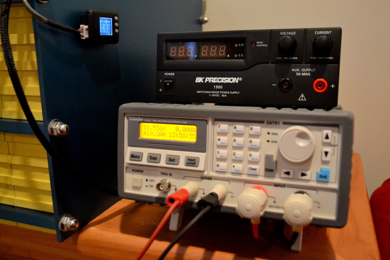
Here’s a close up shot of the data the DC electronic load captures when set to battery capacity testing mode. This data can also be exported to our computer system.
While this is a 40A capable DC electronic load, for testing LFP banks I will set it to 30A so as not to over heat it by running at full-output for 10+/- hours. Sure, the tester is rated at 40A, but like anything electronic it likes to be run at a lower rare, develops less heat, and it will last longer doing so. Again, due to the very low Peukert-like effect of LFP, the discharge rate for capacity testing, is not really of super critical importance so long as you are doing an A to A type test for monitoring historical changes in capacity.
It should be noted that BK Precision charge source and DC Electronic Load Tester both utilize dedicated voltage sensing leads that do not carry any current. This means accurate charge voltages are measured at the battery terminals, and also accurate cut-off voltages are measured at the battery terminals.
The cut off voltage for this particular capacity test was set to 11.6V or 2.9VPC we then moved to 3.0VPC or 12.0V. There is really very little stored Ah capacity below 3.0VPC so for our every 100 cycle capacity tests 3.0VPC is now being used. During testing a well calibrated Junsi Cell Log 8S is typically used to trigger “end of test” if any cell drops below 3.0V. The “hobby grade” Cell Log 8S tends to drift so we calibrate before each test. We also have an ISDT BattGO 8S and it is really no better than the Junsi Cell Log 8S..
The Capacity Testing Process for This Bank:
#1 Charging = 13.8V and current allowed to taper to <10A
#2 Cell Temps = 76F – 77F
#3 DC Load = 30A constant
#4 Voltage Cut Off = 11.6V / 2.9VPC
#5 Capacity Measurements = Ampere Hours & Time At Load
Results:
Cycle Number = 550
DC Constant Load = 30A
Ah’s Delivered = 419.2 Ah’s
Time @ 30A = 13:58:55
Do yourself a favor and create a baseline capacity figure that is both repeatable and useful to you!
Cycle Test #772 Discharge Graph

This discharge curve may be helpful to some. The data is the same data as the video below only in a graphical format. Of interesting note is how little capacity is stored above 3.32VPC, at loaded voltages, under a .075C discharge rate or 30A for a 400Ah rated pack.
Between cycle 550 and 772 the question of LFP memory effect came up in some LFP discussion groups. LFP memory effect is noted in white papers and scientific data where a voltage-hump can occur in the charge curve after many PSoC cycles. To experiment with this bank I ran numerous back to back capacity tests to see if this bank suffered from any “memory effect” in an attempt to erase them, if they were there.
On cycle 772 the bank delivered 432.1Ah’s and did so with an increased cut off voltage of 2.9VPC vs. 2.8VPC at cycle 550. Charge current was allowed to taper a bit lower at 13.8V, down to 7.5A, but other than that the back to back 100% to 0% cycles seem to have allowed a bit more capacity to be realized from the bank.
Some users of LFP who have done continual PSoC use, multiple years of PSoC use, are claiming to be experiencing LFP memory effect. As of right now it seems to not respond or to be erasable. Experiments are on-going and I will post here when I have more hard data on LFP memory effect. I can only surmise that the every 50-cycle 100% to 0% SoC capacity testing has helped keep any PSoC memory effect to a bare minimum. In-between these capacity tests this bank rarely hits a true 100% SoC but does get well into the high 90’s with frequency.
In the graph above the 400Ah rated battery has only delivered 2.83Ah’s by the time the voltage curve levels out at 3.32V under the 30A load. When these cells are at 100% SOC they can have a resting voltage of about 3.38VPC to 3.40VPC or 13.52V to 13.60V, for a 12V nominal pack, but there is really very little stored energy between 3.4VPC and 3.32VPC about 0.65% of Ah capacity to be exact.
On this pack the stored energy between 3.4VPC and 3.32VPC was 2.83Ah’s. This is the rather abrupt near vertical portion of the blue voltage line at the very beginning of the curve. Also, at low rate discharges, such as this .075C discharge rate, the curve is more gradual and it is not until about 2.9VPC that the voltage starts to hit the knee and drop rapidly, in a near vertical fashion.
On a 400Ah rated pack, at a 30A / .075C discharge rate, the working voltage range between about 99.3% SOC and 0% SOC is only a 1.66V difference for this 12V nominal pack.
This video was created using an intervalometer snapping a photo every 2 minutes: It shows the entire discharge capacity test.
Watch This Capacity Test Live
Summary
A lot has transpired since 2010 in the LFP industry. The technology is extremely safe, arguably safer than Lead Acid. The cells do and are holding up to the cycle life claims and the pricing has come way down to the point that a DIY LFP bank costs
far less than lead acid.
DIY LFP Best Practices
- Purchase your cells from reputable dealers who already have cells in your Country
- Avoid Importing Directly from China
- Run Capacity & IR tests when you get the cells
- Always perform a proper top balance
- Use Cell compression in your build
- If you have high discharge loads use a contactor based BMS not FET
- Use a Class T Fuse
- Use charge equipment that can be 100% custom programmed
- If you plan to charge via alternator use an external regulator wit alt temp sense
- Choose the location carefully
- Lose the lead acid mindset!
- Buy your cells from reputable dealers who already have the cells in your country
- Avoid importing directly from China
- Test the cells when you get the for IR and Capacity
- Buy your cells from reputable dealers who already have the cells in your country
Emergency!
We do not want to put this website behind a pay-wall!
Unfortunately, that is where we’re headed if our readers don’t support this site…
Please make a donation, that’s all we ask. Your donations are all we have to fund this web site. Please help to keep MarineHowTo.com a
FREE source of information!
 .!
.!
Do you know any quality person/business willing&able to install a Complete lifepo4 system connected to solar panels in a cargo van? Size of battery bank 200-300 AH. Will be traveling so anywhere in country is posible.
Thank you.
Paul