Preface
This article contains three separate videos that show how to physically program Balmar regulators. The videos are meant to be watched in conjunction with reading this article so the misconceptions and misunderstandings I have identified over the years, regarding these regulators, can be explained with a bit more depth.
MHT RECOMMENDED PRODUCTS FEATURED IN THIS ARTICLE.A.FFILIATE DISCLAIMER
UPDATE: Since this article was written Balmar’s new MC-618 regulator has been launched, to replace the MC-614. The new MC-618 allows programming via the screen on the Balmar SG-200 battery monitor or via the SG-200’s Bluetooth App. It can also be programmed the same way as this article describes.
The Magnetic Reed Switch
For years I’ve listened to customers express concerns about “how difficult it is to program the Balmar regulator“, and I don’t necessarily disagree with this, especially if you’re a DIY or one who does not do this on a regular basis. Even for myself I can find programming a customers, already installed, Balmar regulator a bit tedious.
This article will help:
- Give you higher a comfort level in programming these regulators
- Clear up some of the confusing language in the owners manual
- Provide you with a “Regulator Programming Cheat Sheet“
- Discuss best practices for programming & installing these regulators
- Provide tech tips that will make the process easier.
This article features the Balmar MC-614H but programming & features are similar for the Balmar ARS-5H.
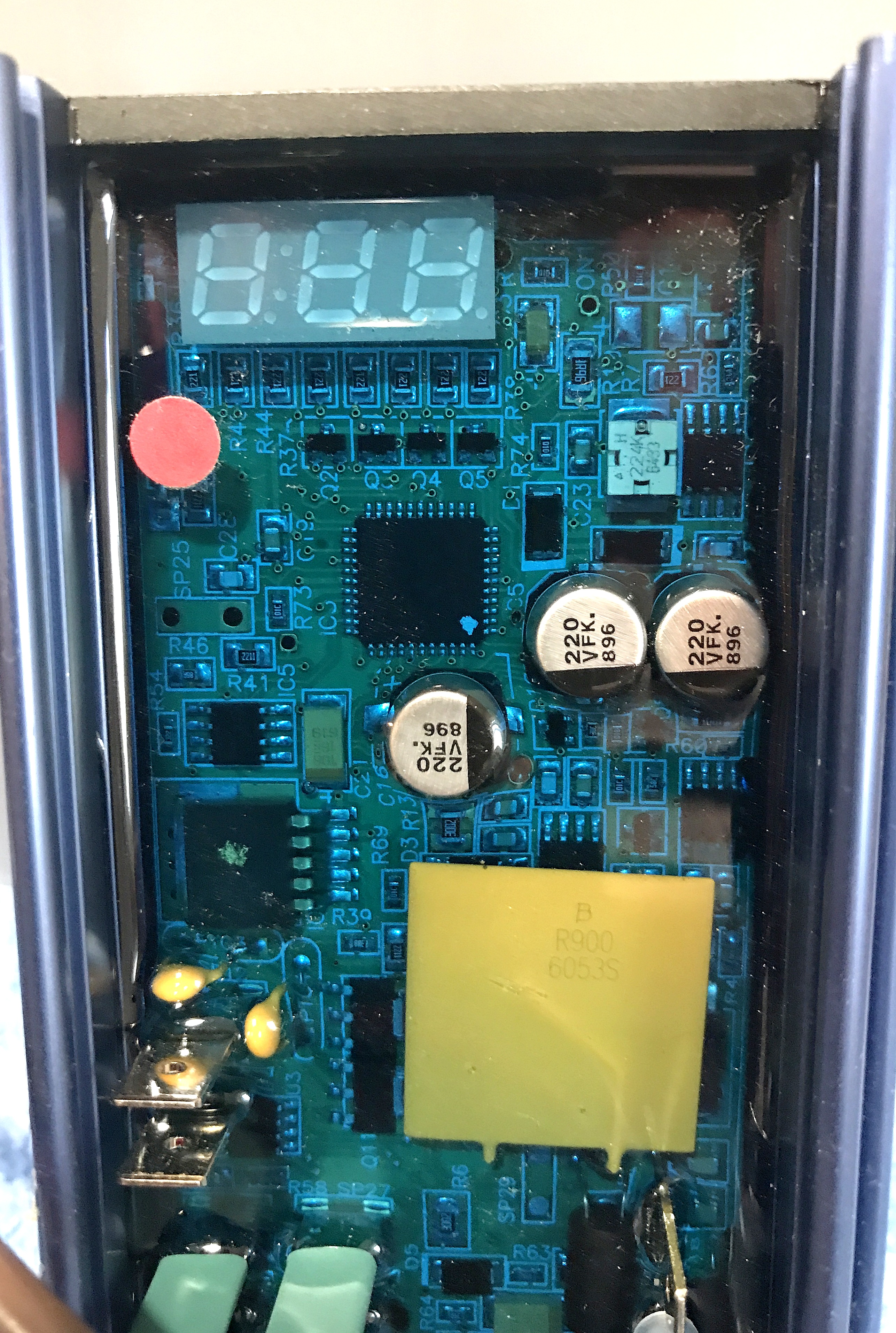
IMAGE: Pictured here is the Balmar MC-614’s magnetic reed switch location, as identified by the red dot.
Definitions: The Balmar owners manuals covers what the LED screen codes mean such as A1C, FFL, AGL etc. etc.. There is no need for us to repeat what is already in the manual in terms of what the numbers/letters are telling you, unless we believe them to be confusing. We have addressed the most commonly confusing parts of the manual, based on years of supporting these regulators, in the article. Please familiarize yourself with the owners manual before reading this article. With the manual and this article it will make more sense.
Why Choose a Balmar Regulator?
Why do I prefer to use the Balmar regulators vs. the other external regulators that are out there? FEATURES! There is no other external voltage regulator, other than DIYing your own, that compares feature for feature with the Balmar regulator. Balmar also delivers excellent customer service and tech-support where humans, that actually know something, answer the phones.
Reliability:
Despite what you you may read on the internet, even by me, because I had an early failure of an ARS-4 & experienced a few others too, these regulators today are very reliable. Over the last 11+ years and many hundreds of regulators I’ve had one regulator with a bad reed-switch (replaced immediately) and one the customer claimed was faulty, but when sent back, was in perfect operational order. Due to changes made over the years to improve reliability, this regulator underwent a full suite of testing, and I got a report from CDI/Balmar. This level of testing was done because these failures are now so rare.
Early on there were some failures of ARS-4’s and some MC-612’s but changes were made to make them more reliable in the move to the current generation. Since CDI Electronics purchased Balmar they have been even further refined for the ultimate in reliability. I’ve not experienced a single regulator failure under the new CDI/Balmar ownership.
Programming & Control:
In today’s day and age there is simply no excuse for any DC charging product that uses “dip-switch” type programming. By dip-switch I mean programming that utilizes a typical three setting; AGM, FLOODED or GEL setting. DC charging products like this, in today’s day and age, are simply antiquated tube TV era products. They really have no place being sold in this century other than to pick your pocket. Please do your best to avoid “dip-switch” set battery chargers, solar charge controllers and external voltage regulators that do not allow you to have full-control over your charge settings.
There are no commercially available external regulators, at this price point, that allow you the same level of programming & control that a Balmar does.
- Base Battery Type
- Belt Load Manager (can also be used for current limiting an alternator)
- Display Mode
- Alternator Failure Advisory
- Regulator Field Start Delay
- High Voltage Limit
- Compensation Limit
- Bulk Voltage Limit
- Bulk Time/Duration
- Absorption Voltage Limit
- Absorption Time/Duration
- Float Voltage Limit
- Float Time/Duration
- Low Voltage Limit
- Field Threshold % Bulk to Absorption
- Field Threshold % Float to Re-Absorption
- Alternator Temperature Threshold Limit
- Battery Temperature Threshold Limit
- Battery Compensation Slope Voltage Correction
The majority of the programming features above are non-existent on other external regulators.
Regulator Installation Best Practices
Balmar regulators use an epoxy potting to keep the regulators printed-circuit-board clean, dry & free from corrosion. Placing it in high-heat areas can increase the risk of the epoxy potting to crack, as shown. I prefer to see a maximum working temp of below 140F, but Balmar claims the regulator can now handle 194F with the newest potting epoxy revision.
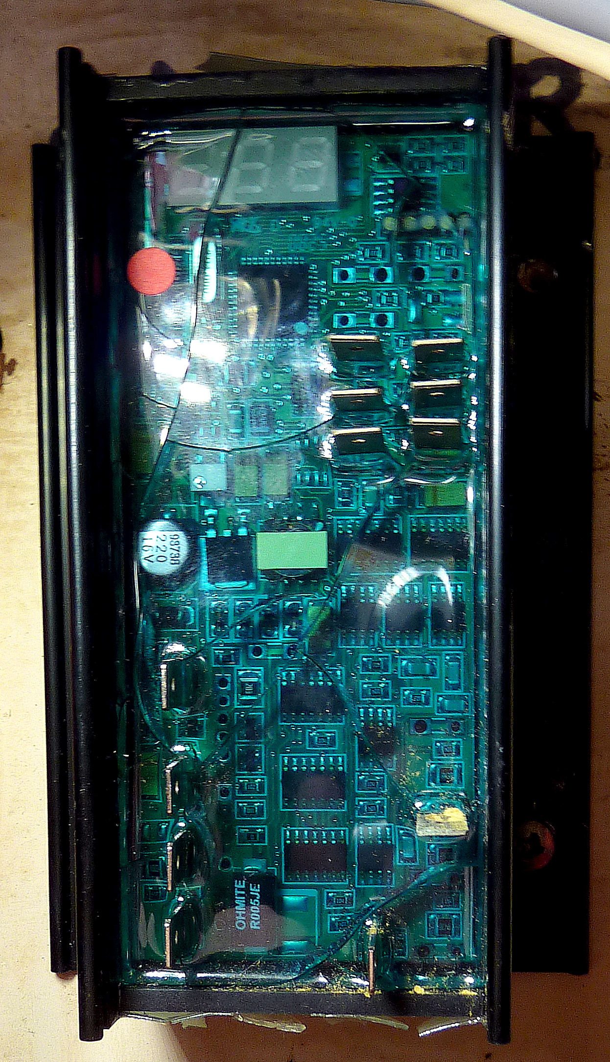
The regulator in the image above was installed by a boat yard, yet it was installed in the engine bay and only inches from the exhaust riser & manifold. The high heat and rapid temp changes caused the epoxy potting, which makes the regulator highly water resistant, to crack. The cracks in the epoxy likely causing one of the traces or components on the PC board to fail.
This regulator was also located near the engines siphon-break and had some corrosion starting on the terminals. This regulator was replaced and relocated outside the engine bay. After replacing it we ran the boat for other purposes and I noted a surface temp where the regulator used be of 208F. This failure is not a result of the regulator but rather a very poorly chosen installation location.
Regulator Installation Worst Practices:
- Avoid installing the regulator in the engine bay unless yours runs pretty cool
- Do not install the regulator in a hot compartment or against the inside of a dark colored hull
- *Do not wire regulator negative to the back of the alternator
- *Do not wire voltage sense to the back of the alternator
- Do not just set a battery type and walk away
- Do not forget proper over-current protection / fusing
- Do not clean the epoxy potting with any solvents
- Do not use Velcro to affix your regulator to the vessel, there are four screw holes for a reason
Regulator Installation Best Practices
- Install the regulator in a cool & dry location, quite often this will be outside the engine bay
- *Wire positive & negative voltage sensing directly to the battery being charged or as close as possible
- Always use the advanced programming menu to get an optimal set up
- Always program the alternator specifically for your batteries
- Program the regulator at home rather than once installed, it give you much better control
- Always use the optional battery temp and alternator temp sensors (MC-614H offers two battery temp sensors!)
- If you need to extend the wiring harness make one yourself rather than adding onto the factory harness with hidden splices
- Always program your regulator to avoid dropping to float too early. I call this “premature floatulation“
- Always use proper crimp tools & terminals
- Always use over-current protection on any positive feed to the regulator Reg B+/red, #9 / v-sense and Brown / ignition
- Try to mount the regulator in a vertical orientation
- Maintain a decent distance from RF noise emitters such as the alternator itself, inverters, chargers etc.
- Allow for adequate air flow around the regulator
- Use the Balmar supplied magnetic screwdriver, it has the correct magnet strength for the reed switch.
*Please read this sister article on proper voltage sensing for the best charging performance.
Alternators & Voltage Sensing Article
Installation Location
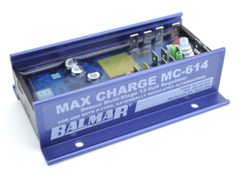
Over the years Balmar has had some varying advice on where to best install the regulator. This particular manual for an MC-614 (see image) says to avoid engine bays due to high heat. I tend to agree with this particular manual, unless your engine bay runs cool and is well ventilated.

MarineHowTo.com Regulator Programming Cheat Sheet

In order to help make the job of programming a Balmar regulator easier, MHT created a programming cheat sheet just for this purpose. This .pdf file allows you to print it, then go through each setting before hand. You simply choose what you want to change/set and enter it into the cheat sheet before you start programming. The cheat sheet follows the MC-614’s scrolling menu.
TIP: When you’re all done programming the regulator, please save your programmed settings by inserting the “programming cheat sheet” into your on-board owners manual. Now any service tech that gets on board will know exactly how your regulator is programmed. They will really appreciate this information and it may just save you a lot of time and money.
IMPORTANT: Please purchase batteries from manufacturers who can provide you with all the parameters necessary for proper programming.
This is a free printable .pdf download:
Regulator Cheat-Sheet Download
Custom Cheat Sheets:
Edit: 1/2/21: This service is by schedule only:
If you would like us to create a custom cheat-sheet for you, the flat fee is $75.00. Before you contact us please read the following;
1- We only do custom cheat sheets for genuine branded batteries such as Lifeline, Trojan, US Battery, Northstar, Odyssey, Crown, Deka/East Penn, Rolls, Fullriver etc.. We do not make cheat sheets for batteries sold by “sticker application companies” such as auto-parts stores, West Marine, Costco, or cheaply made off-shore batteries such as Renogy or most any non USA made battery sold on Amazon. If the sticker on your battery is not an actual physical battery manufacturer, please do not contact us for a cheat sheet.
2- We do not offer custom cheat sheets for LiFePO4.
3- You must provide us with a complete description of how you use the boat, daily Ah consumption, all charging equipment including brand, make, model and amperage. Also, if you have an externally regulated alternator we will need to know what belt you are driving the alternator with and the amperage of the alternator.
Regulator Cheat Sheet Example

In this image, and downloadable .pdf, we have an example of a regulator cheat sheet all filled out and ready to program the alternator for a GEL battery. This is simply an illustrative example of what a filled out programming cheat sheet might look like.
Why is Belt Load Manager a Tremendous Feature?
Belt Load Manager, formerly known as Amp Manager, is a feature unique to the Balmar family of regulators and is built into both the MC-614 and ARS-5. It is programmed using bEL in the regulator programming menu. I know of no other external regulator, other than Wakespeed, that offers any way to limit the alternators current output to accommodate a belt limit situation or to reduce the chances of the alternator from over-heating.
Lets use this alternator as an example:

This owner replaced his 80A factory alternator with a 110A Balmar, only his existing regulator was not a Balmar, but rather a an older Xantrex/Heart Interface. This was a very bad idea. The old Xantrex regulator, like most others out there, had no way to limit the alternators amperage output to better match the v-belts capabilities. The belt on this engine was a 1/2″ or 13MM single v-belt, the standard belt for this engine. Using the factory 80A alternator belt dust was tolerable but two factory alternators burned up trying to feed the massive bank of AGM batteries so the owner sought higher performance.
Once the owner switched to the 110A Balmar alternator he began chewing up alternator belts at a rate of one belt for every 16-22 hours of engine run time. Wow!!!! The belt dust was literally choking everything including the alternator. Alignment was spot on, pulleys were clean and rust/corrosion free and the belt wrap on the alternator pulley was actually quite decent too. The problem was simple, he was just overloading the belt and had no way to limit this issue other than dual v-belts $$$$, a serpentine pulley kit $$$$, or a better designed regulator $$. The owner chose a Balmar regulator and belt manager was set to level 5. Belt dust was nearly eliminated and he went three years on the next belt. Ideally this situation required dual v-pulleys, or a multi-rib / serpentine kit, but with the Balmar regulator and Belt Load Manager, he was able to make it work and at a much lower cost than a pulley conversion.
IMPORTANT: Just because you purchase a 100A alternator don’t be fooled into thinking this is its maximum output. When cold a typical performance based small case alt can pump out 5%-15% more than its face value cold rating or 105A to 115A +, for short duration’s, even with a 100A rated alternator. Some brands will deliver more than 20% over the rating when cold. This overage, even for short duration’s, wreaks havoc on belts. Only Balmar regulators offer the Belt Load Manager feature.
Belt Load Manager solves two important issues:
#1 Limit an alternators output to better match the v-belts HP drive capabilities.
#2 Limit an alternators output in high demand/long bulk situations to allow longer alternator life by running it at less than “full bore/full output”. Contrary to popular misconception we know of not a single small case alternator that can be run at full output for hours on end, unless;
- The rectifier has been removed and the unit is rectified remotely
- It uses liquid cooling
- You are directly force feeding it ice cold air while also exhausting the hot air
For example, if your desire a hot alternator output of 85A – 100A then you would ideally want to purchase a 120A or larger small case alternator and use Belt Load Manager in order to limit the alternator output to your target amperage. Sizing this way keeps your alt running cooler and keeps it within its safe operating envelope, in regards to a safe working temperature. Again, only Balmar regulators have the capability to limit the alternators field potential.
IMPORTANT: Small case alternators are NOT CONSTANT-DUTY RATED.
Don’t be fooled by less expensive regulators which lack features and lack the programming the Balmar regulators have.
Belt Load Manager Misunderstandings?
Below is a direct quote from the Balmar manual:
“The MC-614 provides the ability to manage regulator field potential, making it possible to govern the horsepower loads placed on the drive belt(s) by the alternator. The Belt Load Manager can also be used to protect the alternator from extraordinary load created by a battery load that’s too large for the alternator’s capacity.”
I have highlighted the words “field potential” for a reason and that reason is because Belt Load Manager (BLM), and how it actually works, is very often misunderstood.
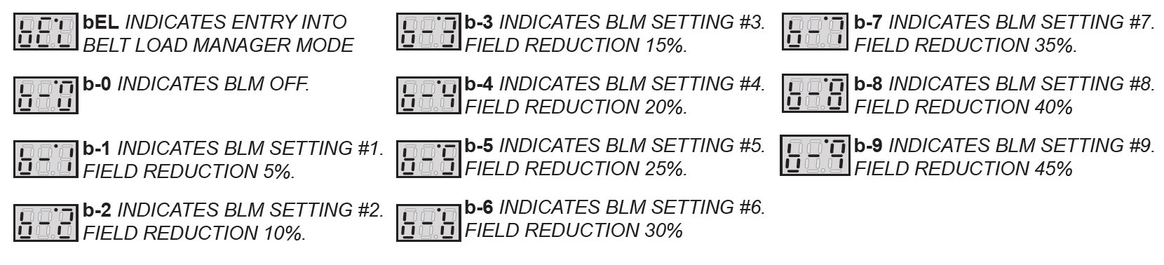
Each step in BLM results in a 5% reduction off the maximum available field potential (click the image to enlarge it). It’s important to understand that BLM is not a 5% reduction in amperage output on a 100A alternator, or a 20% reduction in output for a 150A alternator making the 100A a 95A alternator and the 150A alternator a 120A alternator. This is not how it works, but it’s how many folks assume it works.
What is Often Assumed or Misunderstood
*100A Rated Alternator
BLM #1 = 95A Alternator
BLM #2 = 90A Alternator
BLM #3 = 85A Alternator
BLM #4 = 80A Alternator
BLM #5 = 75A Alternator
*100A alternator used as example only
The reality is this is not how BLM works. We have RPM, rotor core resistance, battery voltage, cold alternator windings and hot alternator windings etc. all playing a role in its overall output and field demand.
As an overly simplified example, consider BLM this way;
If your alternators field could pull max of 6A, at a given RPM, field voltage & stator/rotor temp, and you then set the regulator to BLM #1, the field potential (field voltage), the alternator could see, based on all the previous criteria, is reduced by 5%. This 5% reduction, in avaible field voltage, would result in less than 6A driving the rotor.
What is “Field Potential”?
Field potential, for a Balmar regulator, is battery voltage (sensed voltage) minus about a 0.4V to 0.5V drop across the regulator FET’s. So a battery voltage of 13.5V, during bulk charging as voltage is climbing, results in a field potential of about 13.0V to 13.1V. If we follow Ohm’s law, voltage is what drives our current, and the same is true into a alternators rotor. BLM reduces the available field voltage, measured after the FET’s, by 5% for each step. If we reduce field voltage (field potential) we also reduce field current and alternator output *generally goes down.
*Generally - Occasionally a single BLM step will not reduce output because the regulator is slightly over-driving the rotor to begin with.
Keep in mind that if you set up belt manager, into a hot alternator, it will still produce more current when it is cold. If you set it up at a low RPM it will be different than at a high RPM.
Bottom line is that BLM is a reduction in the avaible field potential (field voltage) not a reduction in alternator output based on it’s “rated output”.
There are a few ways you can program this:
- Reduce BLM in steps, over a few week period, with good solid runs in-between that would be sufficient to generate belt dust. Reduce BLM until you no longer have belt dust or you are no longer bouncing in and out of alternator temp limiting.
- Beg borrow or steal an inverter that can load your alternator to its maximum output and set your engine at cruise RPM. Now use a DC clamp meter or other ammeter to measure alternator output amperage. While the engine is running reduce BLM until you are at your desired maximum output at cruise RPM. It will still be higher when the alt is cold but not for very long. If concerned about cold start load, reduce BLM by one more step.
Belt Load Manager is just PWMing (pulse width modulating) the field output during periods that would otherwise result in 100% regulator field output.
Program The Regulator Off the Boat
One of the easiest ways to program a Balmar regulator is at home, with a 12V source. It is simple, and requires only 4 wires for the MC-614, or 3 wires for the ARS-5. You’ll also want a fuse or fuses to do so this safely. In this image I’m using a small 12V GEL battery. I use this battery for testing mast wiring during spring commissioning. I have added a fuse block and three fuses; Ignition, Regulator B+ and regulator Volt-Sense plus the yellow regulator B-/Negative lead.
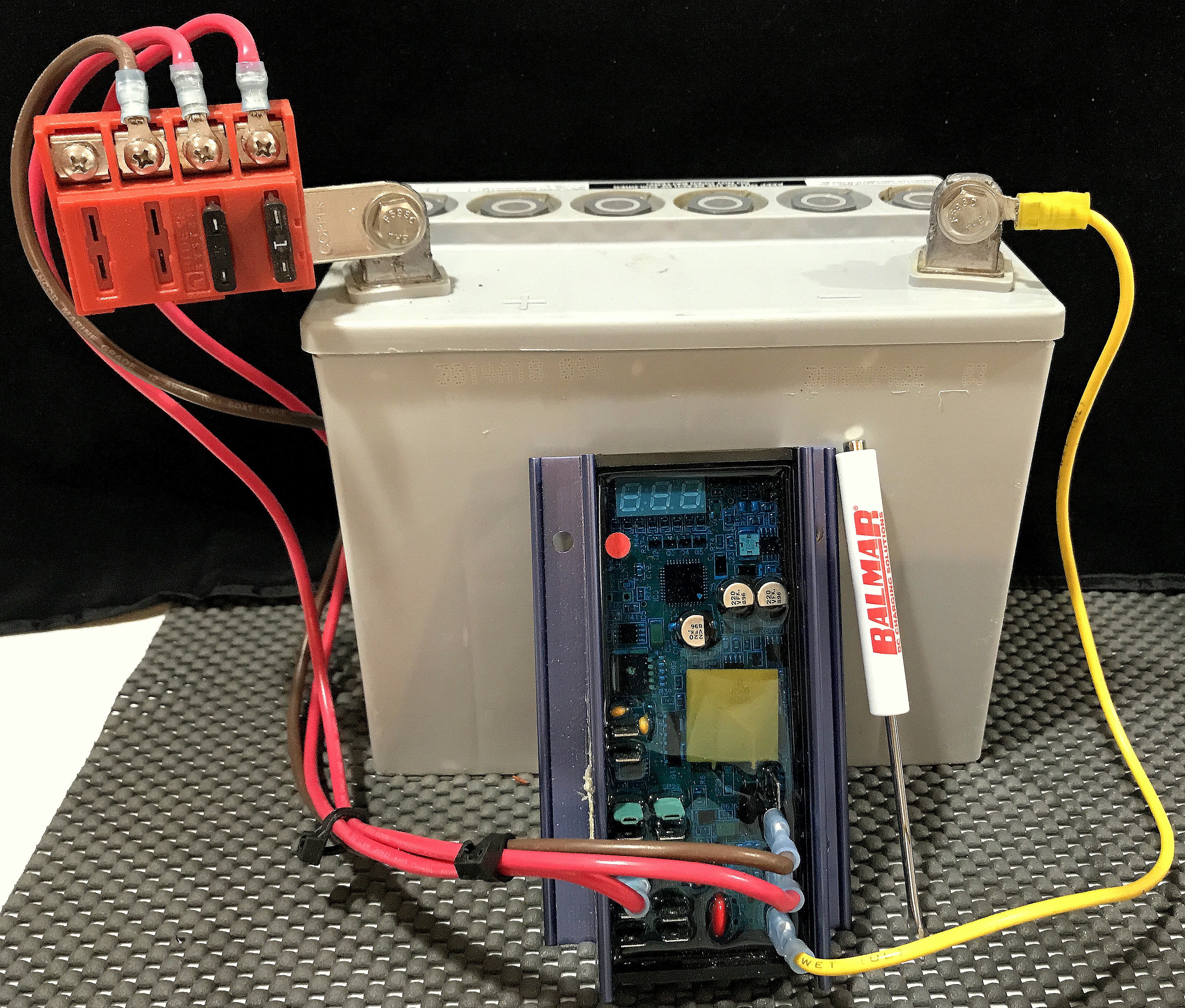
Programming the regulator, in comfort, is much easier, less stressful and you can easily double or triple check your work all while not having a hose-clamp tail piercing your backside. I pre-program every single Balmar regulator I install, here in the shop, before I even get to the boat.
Required Connections for Bench Top Programming:
Regulator B-/Negative – Yellow or Black Wire Terminal #1
Regulator B+/Power – Red Wire Terminal #2
Ignition / Brown Wire Terminal #3
*Voltage Sensing – Terminal #9 (*MC-614 only ARS-5 does not have a terminal #9)
IMPORTANT: Battery or source voltage must be at a minimum of 12.5V in order to program the regulator & have the changes save.
TECH TIP: Please fuse all positive wires (+ volt-sense, B+ & Ignition). Hooking the regulator up backwards, without fuses, can destroy it.
Programming The Base Battery Type
It is best to tackle the programming in three distinct steps with battery type being first:
1- Program the base battery type; bA
2- Program the next three settings of the hierarchical menu; bEL, dSP & bDL
3- Program the Advanced Settings
In the first video the MC-614 is programmed for the base battery type or bA:
The reason for programming the base battery type first is to prevent confusion down the road. Let’s assume you left the regulator programmed to UFP or “Universal Factory Program” but then went in and created a full custom charge profile, in the Advanced Settings menu for your GEL batteries. The first thing a tech will do, when there is an issue, is to look at the UFP setting, then look at your GEL bank, and change the battery type to GEL. They may do this despite the fact that you have proactively changed the GEL or AGM or FDC settings in Advanced Programming, to exactly match your brand & type of battery. Correctly setting the battery type just prevents confusion.
The Programming Hierarchical Menu
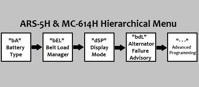
The menu you see in this image represents the top line menu items that you’ll scroll through to program the regulator. Each hierarchical menu item is a gateway to change what that top-line menu represents.
TECH TIP: You do not need to go through each step each time. For example, if you made a mistake setting Belt Load Manager or bEL, but everything else is correct, release the magnet after “PRO” appears, then re-touch at bEL to set or change Belt Load Manager. Once you’ve fixed bEL just let the display scroll three times until you see SAU, which means SAV or SAVE, you’re now all set.
Hierarchical Menu In Scroll Order
bA = Set Battery Type – The gateway to set battery type eg; AGM, GEL, FLOODED etc.
bEL = Set Belt Load Manger Percentage – The gateway to set BLM eg: level 4 is a 20% reduction in field potential
dSP = Set Display Mode – Two choices, long display or short display
bDL = Alternator Failure Advisory – Two choices ON or OFF
— = Advanced Programming – The gateway into advanced regulator Programming which features 15 customizable parameters
This second video examines the hierarchical menu of the MC-614 Regulator:
The third video show how to use Advanced Programming
TECH TIP: For batteries such as LiFePO4 you may find it necessary to reduce the bv setting below the default low of 14.1V. When using the regulators menu in scroll-order this is not possible because Av is set to 14.0V and each step must be 0.1V apart. There is however a work-around for this.
If you wanted to set bv to 13.9V & Av to 13.8V you would need to reduce Fv first, then Av and then you can reduce bv. Each constant-voltage stage, bv, Av or Fv, needs to be programmed with a 0.1V spread. In other words bv can not be set lower than Av or Fv. The work-around is simple, just start backwards by reducing Fv first, then reduce Av then set bv last. Now you can drop the bv, Av & Fv target voltages lower than the factory defaults allow for.
bv = Bulk Target Voltage
Av = Absorption Voltage
Fv = Float Voltage
Confusion Creates Communication Issues
“RC I am fed up with this piece-o-crap alternator.It is in “bulk” and this damn thing is only putting out 20A. How can I send it in for repair?”
The above quote is a typical day in my world. Because the manual and charge lingo Balmar has chosen are confusing at best, trouble shooting time is burned up over perceived issues that are not real all due to semantics.
This all really boils down to two things.
1- Boaters generally understand that “bulk charging” means maximum output from the alternator.
2- Balmar calls a constant-voltage or voltage limited stage of charging “bulk voltage”.
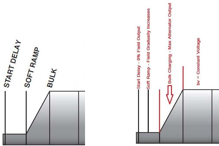
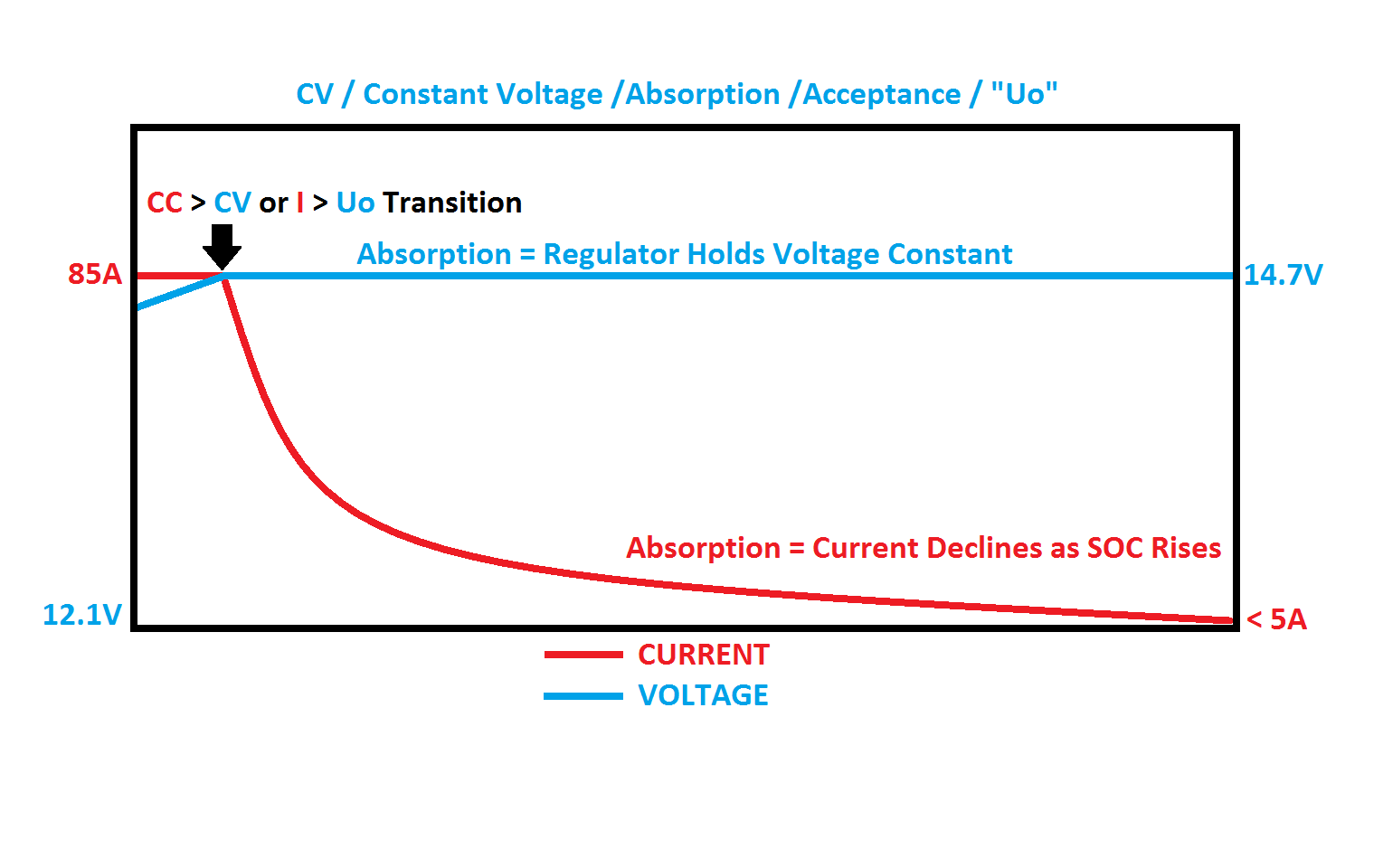
Once voltage is maintained at a constant limit by the voltage regulator ACCEPTED CURRENT DECREASES. Once at constant voltage “bv – bulk voltage” the alternator is not at maximum output. The Balmar charging graph above, and on the right side, has been edited to show what really happens before we attain bv or “bulk voltage”.
Balmar only shows two things happening before constant voltage;
START DELAY
SOFT RAMP
In reality it’s really;
START DELAY – In this stage the regulator is applying 0% field to allow oil for circulation in the engine
SOFT RAMP – In this stage, a max of about 2 minutes, the field (regulator blue wire) is gradually ramped up to the maximum so as not to “slam” the engine with a huge load all at once.
*BULK CHARGING – During bulk charging the alternator is delivering everything it can, in current, to the battery bank. This can take as little as a few seconds for a bank already at high SOC or as long as multiple hours for a large bank deeply discharged.
*This is essentially an entire stage of charging (bulk stage) that Balmar left out of the graph. It is part of what leads to the confusion.
Understanding Battery Charging Lingo
The marine charging equipment industry apparently likes to keep customers “confused“, especially on topics surrounding battery charging. I suspect this is because it keeps the mystique of the “complex wizardry“, that goes on inside the product, a big secret?
In the marine industry almost all manufacturers use what is referred to as CC > CV charging, and this includes Balmar. The DIN standard designations for charging would be I > Uo > U.
CC>CV charging simply means: Constant Current then Constant Voltage
Constant Current = The maximum current the charge source can deliver to the batteries
Constant Voltage = Voltage is held at a constant value by the regulation circuitry
In the rest of the world there’s actually a DIN standards that defines the charging process and it looks like this; I Uo U
I = Constant Current, CC, Bulk or sometimes called Boost Charging
Uo = CV/Constant Voltage, Constant Over Voltage, Absorption, Acceptance or sometimes Topping Charge
U = CV/Constant Voltage, Float, Finishing Charge or sometimes Maintenance Charge
It is important to note that under all definitions, whether DIN or the US terminology bulk charging is not governed by voltage being held steady, it is limited only by the charge sources output capability. During bulk charging, using real definitions, not made up definitions by a marketing department, voltage is always rising during bulk charging.
BULK = MAXIMUM CHARGE SOURCE OUTPUT WITH VOLTAGE RISING
“RC can an alternator really deliver a constant current?”
The answer to this is essentially no unless the alternator and RPM are held perfectly steady and the temp of the alternator stays the same. Despite myself and many others often referring to bulk charging, with an alternator, as “constant current” it’s probably better described as the alternators maximum current potential.
An alternator is affected by many things that a typical fixed-current battery charger is not. An alternator needs a maximum RPM to deliver it’s maximum current output. As an alternator heats up its winding’s lose efficiency and it’s current capabilities drop off a bit. This is why an alternator, or solar for that matter, is really better described as a maximum current potential charge source during bulk charging.
All maximum current potential means is that the alternator is being driven as hard as it can be, by the regulator, and it’s delivering its maximum current potential based on RPM and temperature. The alternators maximum current potential will vary up and down based on RPM, temp etc. however, it is still bulk charging and voltage will always be climbing towards the constant voltage limit. Because Balmar leaves bulk-charging off of their “stages” chart, and the description in the manual is a bit misleading, it can be quite confusing for the average DIY and even marine techs. Whether you choose to call it; bulk charging, maximum current potential, constant potential, constant current or “I” it’s really just a matter of preference. In any of these scenarios voltage is ALWAYS RISING to the CONSTANT VOLTAGE limit. It’s far more simple to just call it bulk but some manufacturers have muddied those waters, including Balmar by calling a Constant-Voltage stage “Bulk Voltage”. Perhaps a better and less confusing term for Balmar’s “Bulk Voltage” stage would be “Absorption 1”, but I digress….
Bottom Line? DURING BULK-CHARGING BATTERY VOLTAGE ALWAYS RISING!
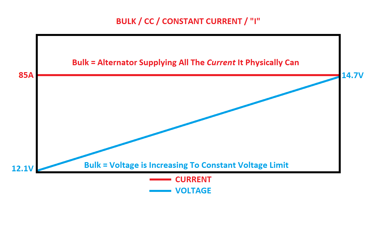
IMAGE = BULK CHARGING: In this image we have a hot 110A small case alternator, held at a steady cruise RPM, and it’s delivering a steady 85A of output (red line). As we can see by looking at the blue line the battery voltage is steadily climbing from the 12.1V it started at (approx 50% SOC) and at the end of BULK-charging it has finally approached the regulators 14.7V Constant voltage limit or the Absorption or Uo stage where voltage will now be held steady by the voltage regulator.
Balmar regulators essentially have two absorption or Uo stages and they are called bV and Av. Balmar’s terminology for BULK CHARGING is “Soft Ramp“… Confused? You should be because it makes little sense based on industry accepted terminology.
Constant Voltage Charging
Now that we have gone over what bulk charging is, it’s also important to know what CV/Constant Voltage charging is.
Constant Voltage = Uo, U, Absorption, Acceptance, Float & Equalization
All of the above words are examples of voltage being held steady or a CV stage of charging. DIN separates Absorption from Float by designating absorption as Uo where the “U” means constant voltage and the “o” means over voltage. The “o” in Uo just means that this CV stage (absorption) can not be held indefinitely or over-charging will result.
The Uo or absorption stage of charging (bv and Av for the Balmar regulators) is one of the most critical charge stages to battery cycle life. The job of the absorption stage is to bring the battery to full charge or very near and to reconvert the lead sulfate, created during discharge, back into active material. The DIN term “U” means Float and lacks the “o” because float can be held for longer periods with minimal risk of over charging.
US Lingo For Three Stage: CC/BULK > CV/ABSORPTION > CV/FLOAT
DIN Lingo for Three Stage: “I”/BULK > “Uo”/ABSORPTION > “U”/FLOAT
To simplify this even more try to consider a voltage regulator as a VOLTAGE LIMITER. All a voltage regulator is really doing, during CV charging, is limiting to a preset voltage point, once the battery bank has attained the targeted voltage.
IMAGE = ABSORPTION CHARGING: This graph is just a continuation of the charge process started in the previous image. To the left we can see the current still steady at 85A (max alternator current output) but the voltage is climbing up to the pre-programmed voltage limit of 14.7V.
Once the battery bank has attained the voltage limit, in this case 14.7V, the regulator switches / transitions from bulk/max current potential to constant voltage charging where the voltage limit of 14.7V is now held steady by the VR. The voltage regulator is now doing it’s job as a “voltage limiter” instead of just driving the alternator to its maximum potential output.
In the graph you’ll notice that once voltage is held steady the current begins declining. This current decline is simply the result of the relationship between terminal voltage, current & SOC (state of charge). In order for the regulator to hold voltage steady, with a climbing SOC, the current being fed to the battery has to decline or the voltage set point would be over-shot. During absorption charging (bv or Av) the battery is dictating what the current can be so as not to “over-shoot” the 14.7V limit. As the SOC of the battery increases less and less current is needed to not over-shoot the voltage limit.
Key Points:
#1 During bulk charging the amount of current available to a the bank determines the bulk duration.
*High Charge Current = Shorter bulk duration and a CC to CV transition point at a lower state of charge
**Low Charge Current = Longer bulk duration and a CC to CV transition at a higher state of charge
*A Lifeline AGM Battery bank charged at 40% of Ah Capacity (160A for a 400Ah bank) will be bulk charging for around 20 minutes. This means the maximum bulk duration is pretty short, the alternator is only at max potential for about 20 minutes and the rest is CV charging where current is steadily declining.
**If we cut the above charge current in half, and charge the same bank at 20% of Ah capacity (80A for a 400Ah bank), the bulk charging duration lasts about an hour and fifteen minutes. Asking any small-frame/small-case alternator to produce its maximum output for 1:15 is pretty tough and it will develop tremendous heat. This is why Balmar offers Belt Load Manager and an alternator temp sensor. Please use them if you have a large or high acceptance bank.
#2 During absorption/CV charging it is the battery that determines the time it takes to get to 100% SOC. The only way to change this relationship would be to increase the target voltage but most batteries have a reasonable limit as to the maximum target absorption voltage.
Programming Tips to Maximize Your Investment
IMAGE: This image is from a reputable deep cycle battery manufacturer and shows their suggested charge voltages for a 12V battery. The 12V battery at 77F is highlighted by the blue arrows. Also note the temp compensation they show in this grid. The temp compensation for this brand is all based on a 5mV compensation (per cell) for each 1°C change in battery temp. If your battery manufacturer can’t provide this information, walk away.

Are you charging your deep-cycle batteries at the optimal voltages for a long cycle-life?
The Balmar regulator is an excellent tool for battery charging but sadly far to many of these regulators are not programmed to work as effectively as they can. These tech-tips can help.
TECH TIPS:
1- Small-Frame Alternators are Not Constant Duty – If you have a small frame alternator and a large bank please use Belt Load Manager AND an alternator temp sensor. Your alternator will last much longer when not pushed to it’s maximum every time it is used.
2- Setting Only bA / Battery Type is Inadequate Programming – Setting a base battery type, and walking away, is about as useless as buying a Bugatti Veyron Super Sport and then installing some 1940’s bias-ply whitewall tires. You’re simply not getting your money’s worth out of the regulator by doing this.
3- Use Alternator & Battery Temp Sensors – These regulators are not complete until you install the alternator temp sensor MC-TS-A, and the MC-TS-B battery temp sensors. Unless you bank is very small, in relation to the alternator, then an MC-TS-A will be a necessary insurance policy. Every battery manufacturer on the planet prefers temperature compensated battery charging, and most reputable manufactures require it. A Trojan battery that charges at 14.8V at 77F – 80F can not charge at 14.8V at 95F. Without a battery temp sensor you run a much higher risk of cooking your battery and causing accelerated plate erosion.
Battery temp Compensation Slope Adjustments: The battery temp compensation feature on the Balmar regulators is adjusted using the SLP or SLOPE feature in the advanced programming menu. This allows the regulator to be programmed for exactly the temp correction the battery maker specifies. One area where folks often get confused is in thinking it is only adjustable from 0-8.3 mV per battery. The 0-8.3 mV is per cell and for a 12V regulator this is 6 cells.
In other-words the regulator setting is adjusting temp compensation slope on a per cell basis, in degrees Celsius, not based on 6 cells or a whole battery. If a battery manufacturer wants 0.002 mV per-cell, per-degree C, this would be 0.012V per battery, per degree C change, but the regulator would be set to 0.002 for slope per cell and would compensate the battery at 0.012 mV per degree C change because it knows it is a 12V regulator and automatically multiplies your setting based on 6 cells.
4- Avoid Premature Float – Setting an adequate absorption/CV duration, (time spent at constant voltage), is critically important to battery health. The factory settings of 18 minutes for bv and 18 min Av plus any “calculated” additional time are not going to help you get the most from these regulators. In a perfect world the “calculations” that can extend or shorten the CV time calculations would work perfectly, unfortunately they rarely do, and this is why there is an advanced programming menu. B1C (bv duration) and A1C (Av duration) can be extended or shortened in the advanced programming, and should be in almost every installation other than LiFePO4.
The algorithm for bv and Av works like this: Programmed time completed/elapsed, regulator field percentage below 65% (or what ever you’ve set it too), voltage has been stable for 2 minutes. Once these three criteria have been met the regulator can now move to the next stage. Please bear in mind that the alternator has NO CLUE what percentage of the field is being used to power on-board loads or to charge the battery! This is exactly why you will need to custom program it so you are getting your money’s worth.
As noted above B1C and A1C time settings, % field and voltage stability (why correctly wired volt sensing is critical) must be achieved before the regulator can move to the next stage, and this is most often a good thing. The factory “base battery type” settings allows for the regulator to drop to float far too early, and I say this with nearly 30 years of experience with these regulators as well as using them as teh default regulator on our alternator testing machine here at Compass Marine Inc… Unless you routinely motor for 6+ hours, when out cruising, you should rarely, if ever, see your regulator drop to float. If it is doing this, you can fix this in the advanced settings menu by extending the minimums on the B1C or A1C time clocks and / or adjusting the field percentages that allow a transition. The only parameter that cannot be changed is the voltage stability the reg is also looking for.
I will often set bv at 0.1V over max factory recommended absorption voltage for 6-18 minutes, depending upon battery type, then set Av to the maximum allowable absorption voltage for anywhere from 2 hours to as much as 5+ hours depending upon the bank and available charge current.
On 3/21/18 I capacity tested a 2014 100Ah TPPL AGM battery that has been charged “properly“. Properly defined as a minimum of .4C in charge current (40A for a 100Ah battery) per manufacturer minimum current guidelines. Bulk-voltage bv is set to 14.8V bv for 12 minutes, then to 14.7V Av for 5 hours. This is 5:18 at constant voltage, temp compensated and an alternator float of 13.8V. The other charging equipment on the boat is solar, set similarly but a 2 hour absorption vs. 5 hours (due to the low current), and with float set to 13.4V.
The battery delivered 96.54Ah out of it’s 100Ah rating. A month earlier I tested a 2016 version of the identical battery. It had been charged only by a stock Hitachi alternator only. It delivered 56.83 Ah’s. The correct absorption voltage and a long enough absorption duration matter and can make big differences in bank longevity.
Yes, the Balmar regulators “try” to maximize and deliver a correct constant voltage duration but, in most cases, they fall short and drop to float far too early. The reason for this is simple, all the regulator knows is voltage and % of field drive. Voltage is simple, but the % of field drive actually being used to charge the batteries is nothing more than a crap-shoot guess for the regulator. What I mean by this is the regulator only knows a voltage, as sensed by regulator + sense and regulator B-, and the percentage of field output. What if 60% of that field output was being used for a water-maker, refrigeration, inverter, or other house loads? What if there were no house loads on at all? What if they turn on and off throughout the charge cycle? You can spend lots of time messing with field percentages but they change and you may not be happy with the results.. The easiest way around premature float is to extend the constant voltage time parameters in either b1c or A1c.
“So what’s the bottom line?”
If your regulator is dropping to float before the batteries are accepting less than 1% – 2% of Ah capacity, at ABSORPTION voltage (NOT float) then it is dropping to float too early. Most AGM’s are between 0.5% of Ah capacity (Lifeline) and 0.3% (Odyssey, East Penn/ Deka etc.) of Ah capacity to use tail current as when to drop to float.. Control this via b1C or A1c or field percentages, if you decide to experiment with field percentage. Extending the A1c duration is generally the easiest method.
Charging Batteries Correctly is Critical
5 – Set Yourself Up For PSOC Success – Using the highest absorption voltage the battery maker allows for will result in the least PSOC (Partial State of Charge) damage to the battery. Even the fastest charging AGM batteries require approximately 5.5+ hours to go from 50% DOD to 100% SOC, and this is in lab conditions with no chance of premature float and with 20% to 40% of Ah capacity in charging current. Flooded & GEL batteries charge even slower so absorption times will need to be adjusted to suit the batteries. The worst efficiencies for charging are from 85% SOC to 100% SOC and this duration alone, the last 15%, even with AGM batteries, often takes 3 – 6+ hours depending upon battery state of health. In the ideal set up your batteries don’t drop to float until they are 100% full. With voltage regulated charging this is tough but we can certainly do better because the MC-614 and ARS-5 regulators can be programmed eight ways from Sunday with ample opportunity to minimize premature-floatulation.
6 – Over Charging Concerns – If you’re concerned about “over-charging” when you leave the dock “fully charged“, which is really more of a personal problem rather than a real problem, simply install a dash switch that interrupts the regulators brown wire or ignition feed to shut it down. If you want to further complicate a relative non-issue you can use a resistor in the battery-temp compensation circuit to trick the regulator into a lower voltage by making it think the battery is hot. I call this trick “switch triggered float”..
I’ve autopsied piles and piles of batteries, both sealed and non-sealed, and the number of “dried-out” VRLA batteries (GEL or AGM) I have seen have been an n=2 banks. Both of these banks were ruined by controller-less solar systems (no charge controller at all) pushing 15+V every day. These batteries were not ruined by voltage regulated alternators leaving the dock at 100% SOC. By far and away the biggest concern with marine batteries is chronic under charging. The Balmar regulators can be programmed to help you avoid this.
7- Utilize Balmar’s Advanced Programming Menu – If you’re not taking advantage of the advanced programming features, ones you’ve actually paid for, you’re really only seeing a marginal, if any, gain in actual charging performance.
8- Wire the Voltage Regulator Correctly – I hear lots of belly-aching over short bulk charging. In every single case of this I find the voltage sensing circuit wired INCORRECTLY. In regards to charging performance, even the Balmar manual is incorrect on how to properly wire voltage sensing. This article cannot be over-looked: Alternators and Voltage Sensing – Why it Matters
9- Field % Transition Thresholds – For a DIY, with not a lot of electrical experience, I generally advise extending b1c and A1c time clocks and leaving the Field Percent Transition Thresholds, FbA (Bulk to absorption) and FFL (from float back to absorption) alone. However, please don’t take this as a blanket statement and don’t be afraid to experiment with the field transition percentages. They are easy to re-set to the factory default, if what you changed does not work.
The difficulty with field percentage transition thresholds is the regulator has no idea what percentage of the field is being used for charging the batteries and what percent of field is being used to power on-board house loads. It is, after-all, a voltage regulator not a current regulator. If your house loads are very predictable, you can easily get the field transitions to work well, but it may take some experimenting and time to dial it in just right. If you run large inverters while under way or have unpredictable loads, while charging, it may be tougher, but please don’t be afraid to experiment with it.
10- It’s All About the Correct Voltages – For years the flooded deep cycle battery industry was stuck in the dark ages as to how to correctly charge lead acid batteries that were used in a PSOC environment. This is because industry and stationary systems require slightly different charge profiles than do PSOC use situations. Today, thanks to folks like Tom Hund (retired), of Sandia National Laboratories Photovoltaic Department, we now know that in order to correctly charge deep cycle flooded batteries we need significantly more terminal voltage during absorption than the antiquated 14.1V to 14.4V old-school guidance used to suggest.
Sadly no-one has keyed in the majority marine charge equipment manufacturer’s about this “breakthrough” information. In their defense, we’ve only known this for 20 or so years. (grin) With a Balmar regulator you can program to your hearts content and get it right.
If you’re not charging deep-cycle flooded batteries at 14.6V (bare minimum) to 15.0V, for PSoC use (boats, RV’s or off-grid solar), they’re simply not getting properly charged. Even many AGM batteries are capable of being charged as high as 14.7V and their health is vastly improved by doing so. With all that said, use your battery manufactures recommended voltages but stick to the maximum of the safe-range not the low side. For example if your battery maker suggests an absorption setting of 14.4V to 14.8V you’ll want to be at 14.8V end of the spectrum not at the 14.4V end.
Proper Programming, It’s Your Choice
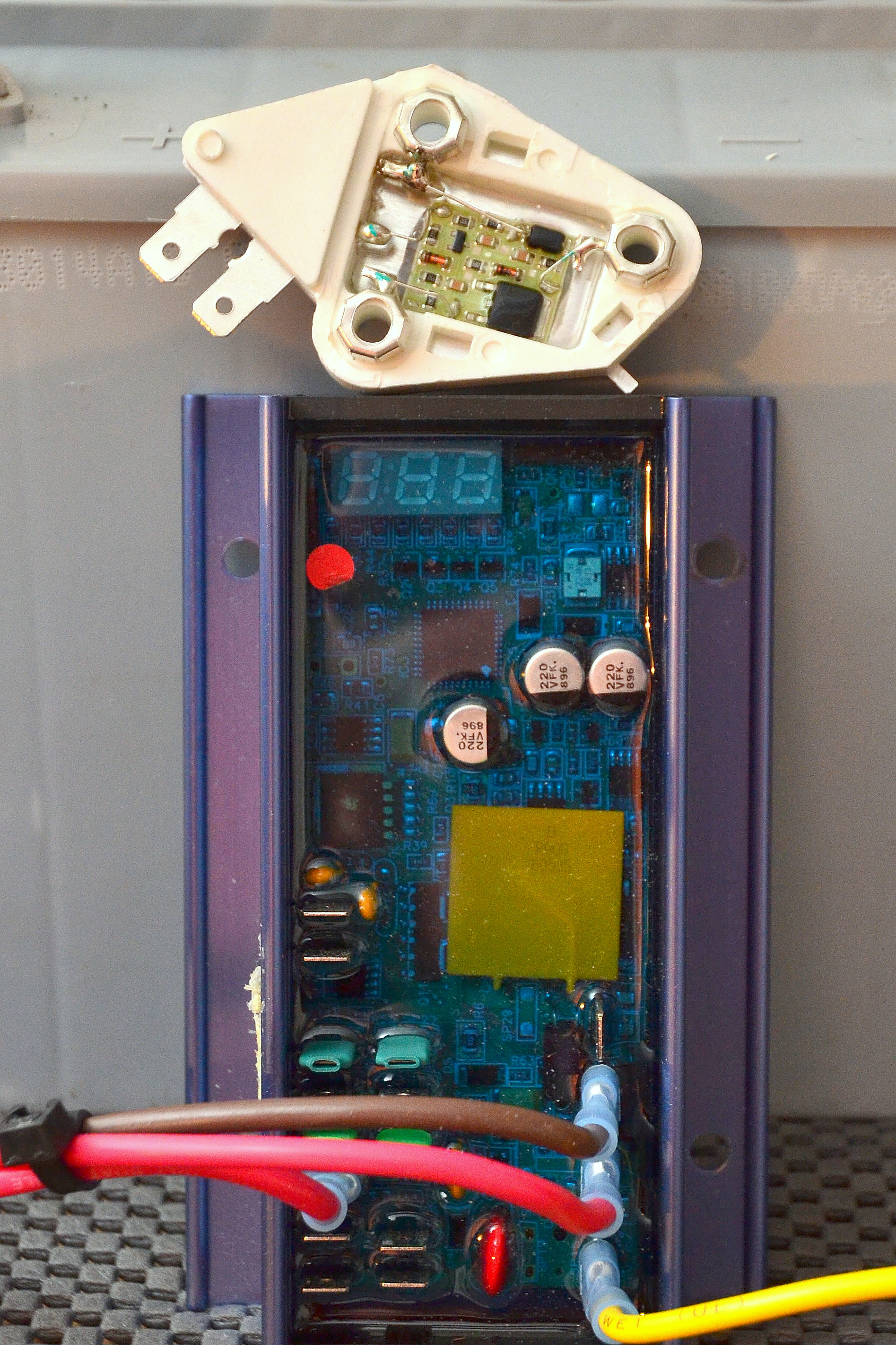
IMAGE: Pictured here is a typical automotive voltage regulator the type found on most marine engines as they ship from the factory. I busted it open and extracted all the potting material so you could see the difference. With this image it is easy to understand why an external regulator, with all the features the Balmar’s offer, can lead to better and healthier charging for deeply cycle batteries and to better protection for the hard working alternator.
In the end it is your boat, and you’ll need to decide how you want to program your regulator, for your own piece of mind. All I can say, as a marine energy management specialist, is that I find far too many external regulators inadequately programmed & wired for the owners to be “getting their money’s worth”. Get your money’s worth and venture into the advanced settings!
SITE PLUG: Please keep in mind that MarineHowTo.com is a 100% FREE SITE with no paid advertisers. This site is 100% reader supported through donations, by the hand-full of products manufactured by Compass Marine Inc. and by products I like, use or can stand behind and add to the store.
All of the products sold to support the web site can be found in the;
MarineHowTo.com Web Store
Please do your best to support this site by making your purchases here. If you don’t see it, just ask; compassmarineservices AT gmail DOT com
Happy boating!
Emergency!
We do not want to put this website behind a pay-wall!
Please make a donation, that’s all we ask. Your donations & affiliate purchases are all we have to fund this web site. Please help to keep MarineHowTo.com a FREE source of information!