The 1/BOTH/2/OFF Switch
Preface: I’ve seen & read many on the internet suggest that “The 1/2/BOTH is RC/Rod’s/Compass Marine’s preferred switching method”.. Let me be clear on this point; this is not our preferred method, it is simply a method. This article is only intended to showcase how the 1/2/BOTH switch can be used in an easier and often less confusing manner. Many boat owners don’t have the luxury of starting from scratch and the existing switch can usually be re-used/re-purposed easier, and in a less costly way, than converting to an entirely new switch configuration..
MHT Recommended ProductsAffiliate Disclaimer
Buy Blue Sea Products – Amazon
Design Principles for Battery Switching:
1- Bank Isolation – The ability to isolate a battery bank from both loads and charge sources in the event of a bank or battery failure.
2- Cross-Connection Use – The ability to use either on-board battery bank as the sole use bank, meaning it serves as starting and house load bank in an emergency, This design criteria should always include #1.
3- Ease of Use – A battery switching design is no good if the boat owner does not understand it.
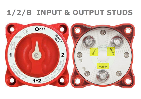
One area of confusion we see fairly routinely is a boat-owner misidentifying the 1/2/B switches terminals. A 1/2/B switch has just three terminals and four positions.
Terminals:
Bank 1 – Input stud 1 in photo
Bank 2 – Input stud 2 in photo
“C” Post – Output stud in photo
“But RC where does DC ground connect to on the 1/2/B?”
If I had a dime for every-time this question was asked, I’d not be writing this article. The 1/2/B is switching only the DC positive conductors and has nothing at all to do with DC negative. Please DO NOT connect DC neg to a 1/2/B switch!!
Terminology Used In This Article:
1/2/B – A battery switch that has position 1, 2 OFF and a paralleling feature often called BOTH, COMBINE, ALL or 1+2
C Post – The “C” Post is the COMMON post which is also referred to as FEEDER, COMMON or OUTPUT
Both – When the switch is set to 1+2, BOTH, COMBINE or the ALL position both battery banks are now physically wired in PARALLEL
1/2/B Switch; a Very Common Factory Wiring Configuration:
Over the years most all boat builders, of both sail and power, have installed the simple and redundant 1/2/B switch. The switch, I believe, has gotten an undeserved bad rap over the years. Why? It’s really not necessarily due to the switch itself, but rather due to the way most builders install them, and the way many boat-owners have used them.
Despite the bum rap, the 1/2/B switch remains a versatile & redundant single-switch battery selector. Surprisingly, even today, they are still the #1 selling multi-bank switch. The 1/2/B offers more redundancy and isolation than just about any other easy to use configuration. The “easy to use” part is arguably debatable. It should be easy but lack of a complete understanding leaves many boaters confused.
1/2/B Switch ConfusionCan Result In:
- Unnecessary Switching & Forgetfulness
- Two Dead Battery Banks at the Same Time
- Damaging Voltage Transients
- Forgetting to Charge a Bank
Confusing Lingo:
START & HOUSE Banks – Like anything in the marine market the 1/2/B can develop it’s own levels of myth & lore. One of the most common misconceptions is that you have a Start Bank and House Bank. Sure, you can assign a switch position to HOUSE and START but they are really EVERYTHING banks. A “START” battery, by definition, is really dedicated to only starting an engine, no house loads.
If you wish to continually move the switch from 1 to 2 then 2 back to 1 etc. etc. it may feel like you have a START & HOUSE bank but you really don’t. In the #1 or #2 position each bank serves both starting and house purposes. Starting and House services cannot be isolated from one another with a 1/2/B unless you add another ON/OFF switch. It is for this reason that we refer to the banks, with a 1/2/B as HOUSE and START/RESERVE. This is still actually incorrect terminology, but a bit more accurate. As you read on you see more of what we mean by this. Technically, and accurately speaking, you have Bank 1 & 2 and each of those positions do both house and starting duties simultaneously.
Builder Blunders?
The 1/2/B switch, as wired by most builders, becomes a Bank Selection and Charge Directing switch. This means what ever position you have the switch set to, is where your on-board energy comes from, and where the engines alternator sends its charge current.
What Bank Selection and Charge Directing Mean:
1/2/B Switch Set To;
Bank 1 = DC loads are drawn from bank #1 and alternator charging goes to bank #1
Bank 2 = DC loads are drawn from bank #2 and alternator charging goes to bank #2
BOTH = DC loads are drawn from BOTH banks and alternator charging goes to BOTH banks
OFF = Both battery banks are isolated/OFF
Note: Even when set to OFF a bilge pump, propane sniffer, stereo memory or VHF may still be direct wired to the house bank so the vessel may still have live 12V wires..
Typical Factory Wiring:
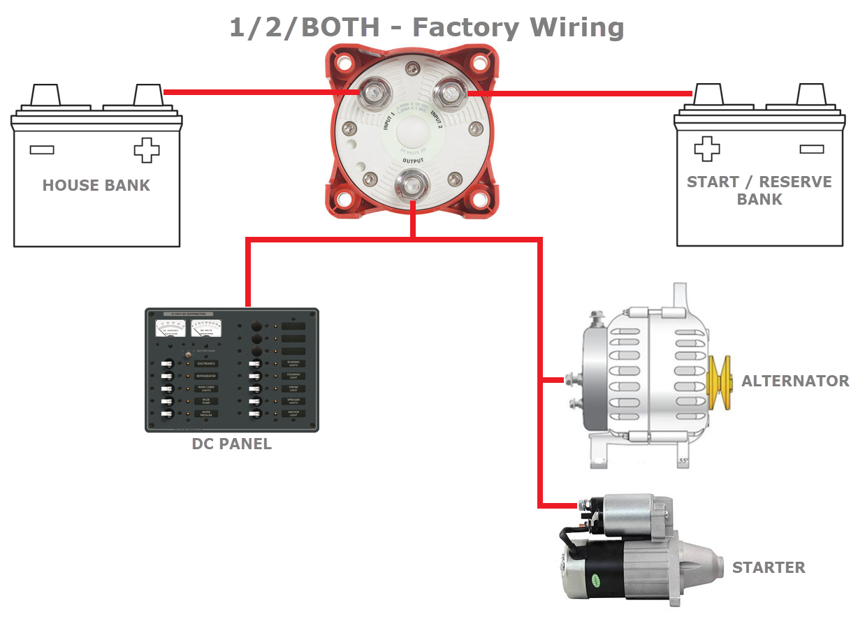
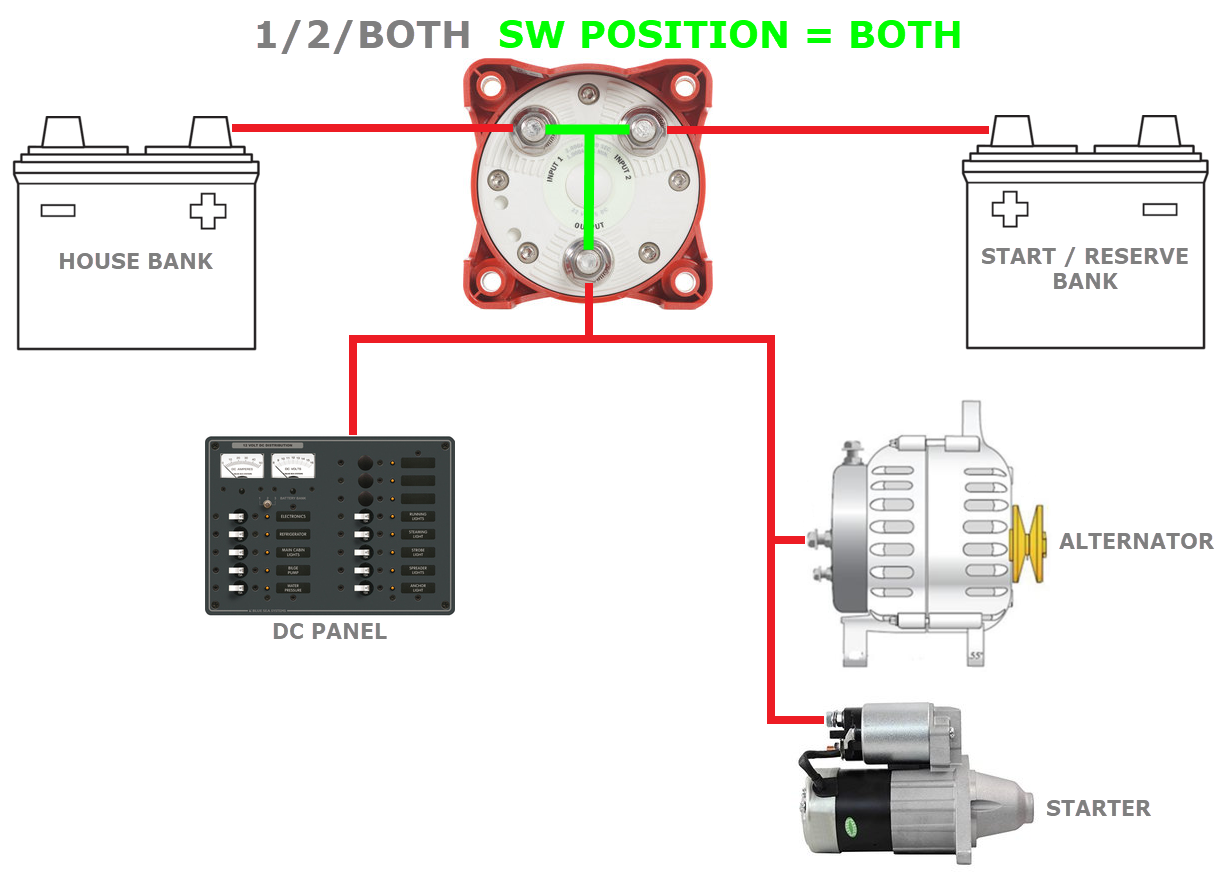
Most boat builders simply wire the alternator circuit back through the starter feed wire to the “C” or common post of the battery switch. The “C” post is energized when you flip to 1, 2 or BOTH and is isolated or disconnected when you switch to OFF. This wiring method is cheap & easy for the boat builder, but leaves owners with lots of room for human error and misunderstandings.
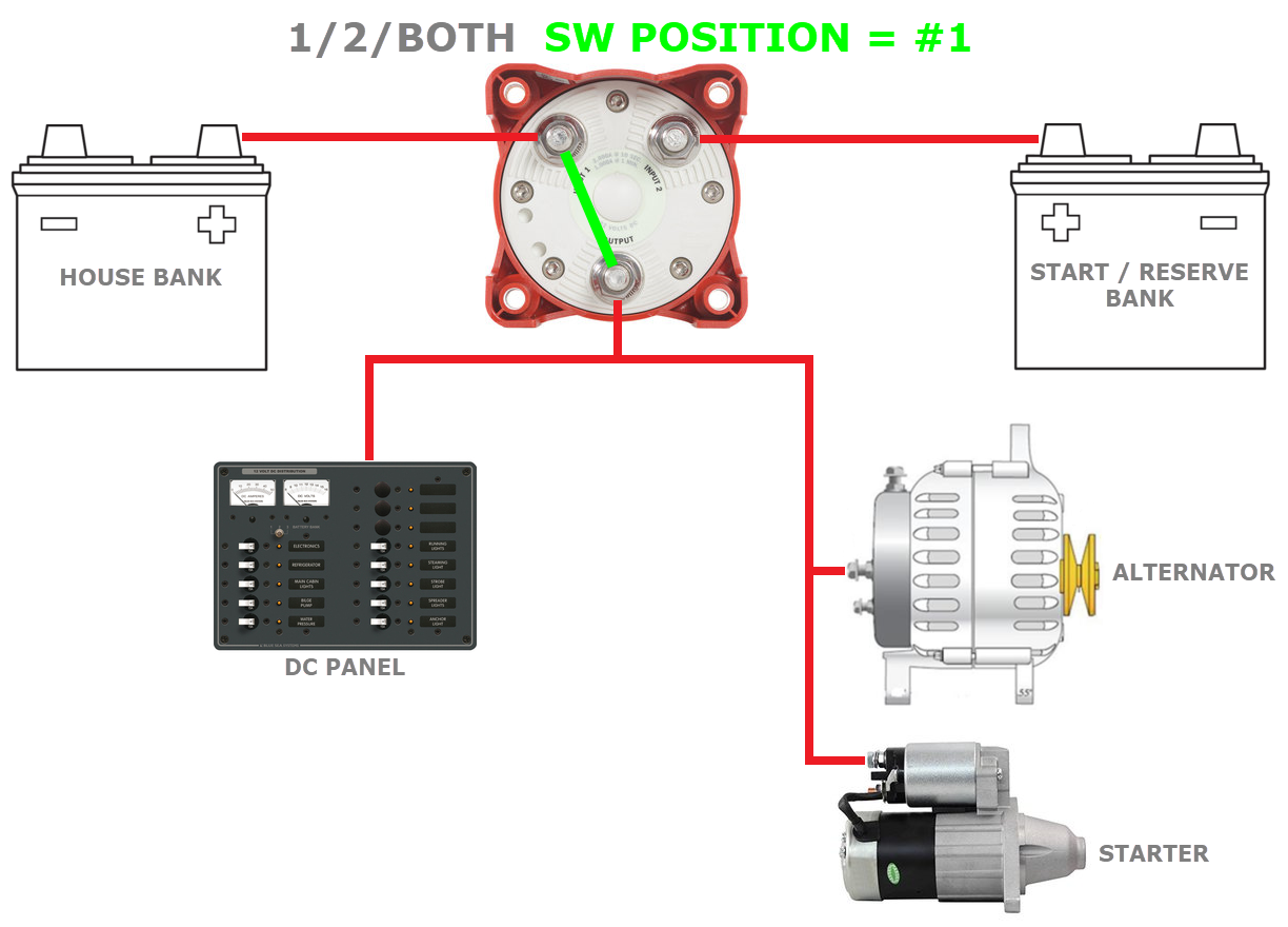
The factory wiring works simply, and allows you to choose which bank you are charging or drawing from by selecting that bank, or both, on the switches face-plate. In the drawings below, the green lines are showing the 1/2B switch connecting the alternator, starter motor and the DC panel loads, to the bank or banks selected, via the “C” post of the battery switch. You can visually see the path the alternator takes to get back to the battery bank. The green lines represents the switch position.
Set it to bank #1 and bank #1 gets charged/discharged
Set it to bank #2, bank #2 gets charged/discharged.
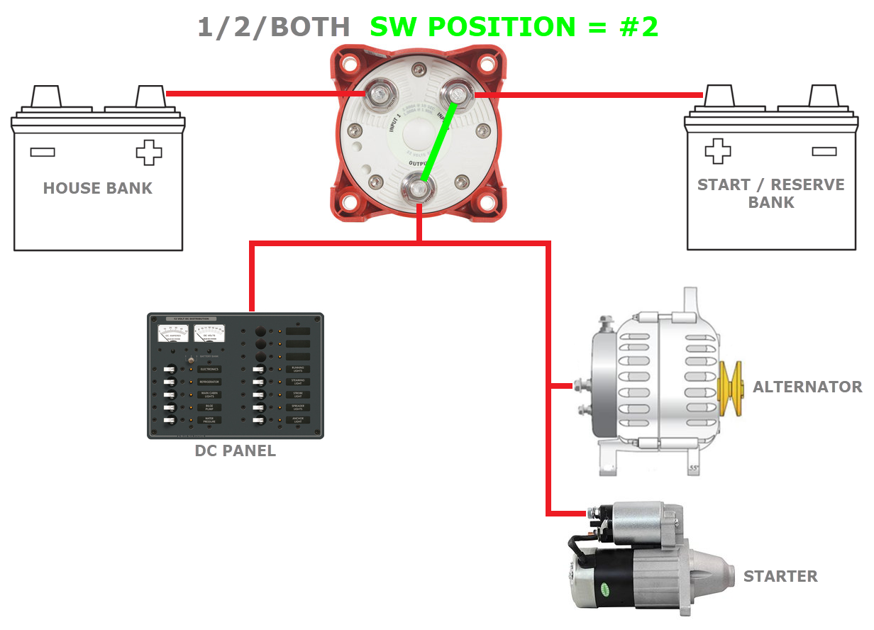
In BOTH and both banks get charged/discharged.
Mishaps and Human Error:
Mishaps and human error creep in when an owner forgets to manually switch & charge bank #2 and now bank #2 never gets charged. Far too often an owner will leave it on BOTH, and then run both the banks completely dead. If this happens, and it does, you’re $hit out o-luck…. We call this the Human Error Factor or HEF.
Owner Blunders?
So why may the factory wiring method be a poor choice? It’s not necessarily poor choice, if you understand your system and how to use it.
Human Error Blunders;
Blown Alternator Diodes & Voltage Transients:
This big blunder happens when you, or a crew mate, tries to switch to another bank and pass the battery switch through the *OFF position, even momentarily. With the engine running and the alternator charging this creates an open-circuit between the alternator and the load (load = battery bank) it’s charging. Momentarily passing through OFF, or disconnecting the load from the alternator, can cause a massive voltage spike as the load/ battery bank is disconnected from an alternator. This quite often results in damaging the alternators rectifier diodes & rendering it non-operational near instantly. it can also damage sensitive electronics that are connected to the “C” post of the switch.
*Most quality 1/2/B battery switches, from reputable manufacturers like Blue Sea Systems, BEP/Marinco, Guest & Perko, are designed to be make-before-break. Make-before-break means that as you turn the switch from position 1, to BOTH or 2, the previous position does not open-circuit or disconnect until the next position can carry the current.
As some battery switches age they can wear and become break-before-make. For this reason it is not a good idea to move the switch while the engine is running unless you perform an occasional make-before-break test. The best way to test your switch is to turn on the cabin lighting (incandescent bulbs work best not LED’s) then slowly rotate the switch from 1 to BOTH to 2. If the incandescent light/s flicker at all during this rotation, replace the switch. Even a fraction of a second disconnect is enough to cause an alternator load-dump.
The Load Dump:
Picture, if you will, a Top Fuel Dragster. The drag car is moving at 200 MPH when it smashes directly into a 10′ thick solid concrete wall. All that energy/mass, and no where to go, means instant destruction. The concrete wall is akin to what happens in your alternator when you shut the battery switch off during charging, especially high-current bulk charging. This open-circuit event, between the battery and alternator, acts as the concrete wall and all that energy has nowhere to go. The result with an alternator is that this energy has to go somewhere, so it skyrockets the voltage instantaneously. The result of an open-circuited battery switch is called a load-dump. A load-dump creates a very fast voltage spike/transient that can destroy the rectifier diodes. Here at Compass Marine Inc., we repair quite a few alternators each year due to battery switch load-dump blunders.
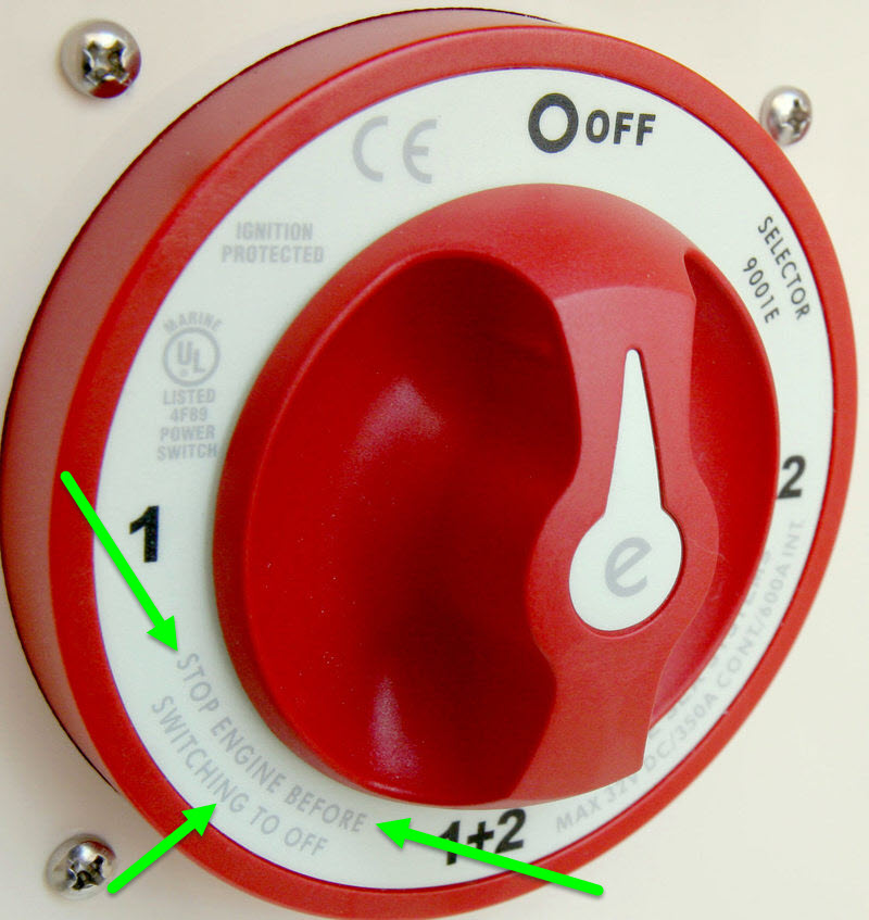
Ever wonder why a 1/2/B switch has this warning? Well, now you do…
Damage to Sensitive Electronics:
Unfortunately it’s not just alternator diodes we need to be concerned with, in a battery switch disconnect / load-dump. A lack of charging is what most owners notice first, but the damage may not end there. If you take a look at where your DC loads are connected, this just happens to be the same exact place as the factory wired alternator, the c-post. When the switch is accidentally opened, while charging, the alternator is instantly disconnected from the battery and all that energy has to go somewhere. Where does it go? Follow the diagram below and you’ll see.
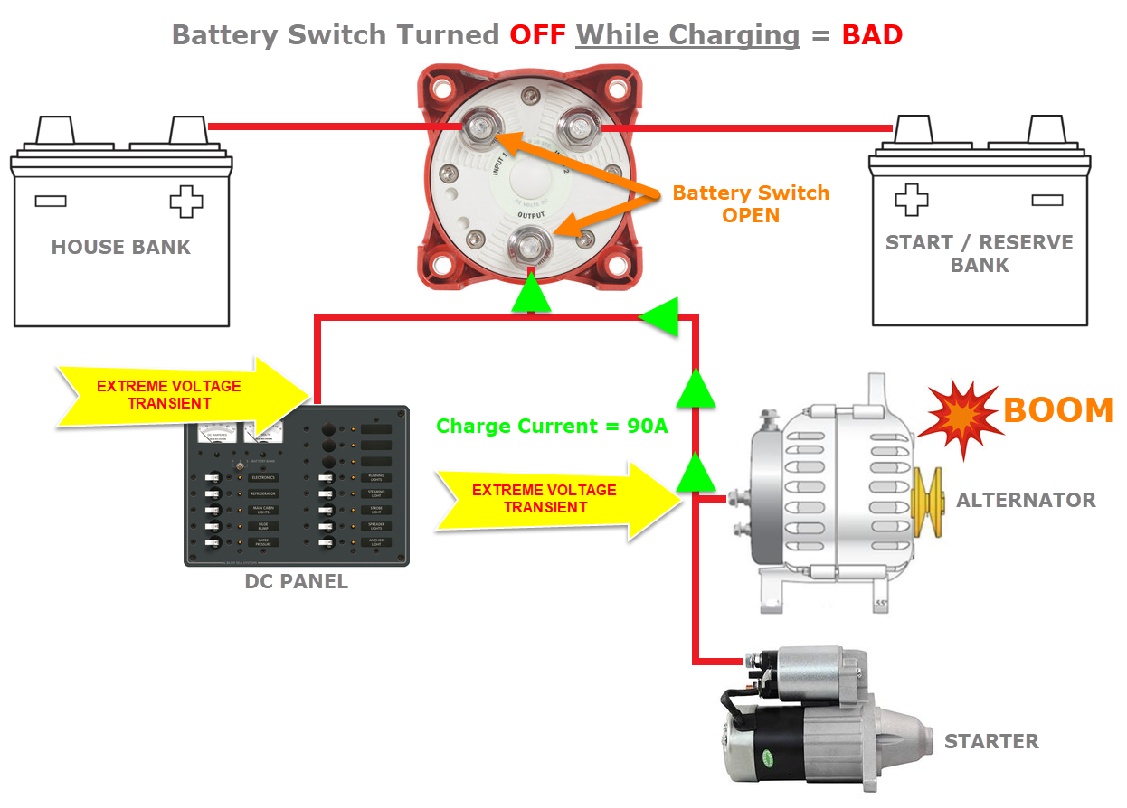
The voltage transient/spike that’s created by accidentally opening the battery switch, while charging, goes straight into your sensitive DC electronics because the alternator and DC panel are connected to the same c-post stud, which is no longer connected to the battery/load. The voltage transient from a battery switch disconnect often destroys the alternator diodes and it can also damage or murder your sensitive DC electronics. It’s not uncommon for us to find multiple other items damaged when a customer comes to us for a bad alternator, and the diagnosis is blown rectifier diodes.
In theory, the voltage regulator would react and stop this voltage transient, after all they do limit voltage, but the spike happens far too fast for the voltage regulator to react. This damaging transient occurs in microseconds. As you now know, when you open the battery switch, while charging, there is a high likelihood the diodes in the alternator will be blown. A mistake like this can leave you with no alternator and potentially ruined navigation electronics too. Sadly the factory wiring does nothing to limit or protect against this. Some newer alternators, on late model engines, utilize avalanche-diodes. Avalanche diodes are more durable and designed to limit the voltage transient, but most existing marine alternators do not utilize avalanche diodes..
Alternator Field Disconnect:
Some battery switches even feature an Alternator Field Disconnect or AFD feature. The AFD consists of two terminals that break the alternator field or external regulators power wire slightly ahead of the 1/2/B’s OFF position opening. Unfortunately, most vessels with see with AFD switches are either not using it or the AFD circuit is wired incorrectly. If you don’t have access to the field wire, inside the alternator, the AFD feature does you no good.
We’ve even seen alternators where the factory alternators key-on excite-wire was passed through the AFD circuit yet the diodes were still blown. Why? The excite wire is only needed to get the alternator started. Once the alternator is spinning, and producing power, cutting +12V to the excite-wire does not always de-power the regulator, and the alternator keeps on chugging away.
Alternator Protection From Load-Dumps:
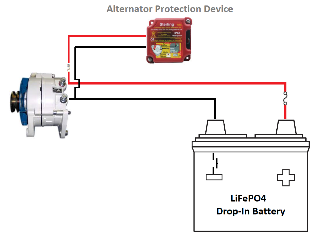
If you wish to keep your 1/2/B factory wiring, and you understand the nuances, it would be a very wise idea to install a Sterling Power Alternator Protection Device. The Sterling APD is designed and intended to clamp or limit a voltage spike/transient to a safe level and protect both the alternator and other DC components.
Here the Sterling Alternator Protection Device is shown with a LiFePO4 drop-In battery. Drop-In LiFePo4 batteries have internal BMS switch (battery management system switch) that can essentially do the same exact thing as flipping a 1/2/B switch through the OFF position. Installation is as simple as two wires and a fuse, and it’s inexpensive insurance.
The “I Must Set it to BOTH to Start the Motor” Mind Set:
Sometimes blunders are just caused by a cascade effect. The “I Must Set it to BOTH to Start the Motor” is typically flawed and unnecessary. At the same time, it’s a reality in some owners minds because the BOTH position acts as a Band-Aid for weak batteries or a poorly wired system.
In the case of starting a motor, the BOTH position is typically hiding or covering up other issues and does not actually solve the issue at hand. On the flip side, it leads to a cascading effect where forgetfulness can lead to error. The “You must use BOTH to start.” mantra has actually climbed to urban-myth status level.
You Should Not Need to Use BOTH to Start Your Motor!
If you need BOTH banks to start your motor, you have other issues such as:
- Failing Batteries
- Batteries Not Sufficiently Sized to Start Your Engine
- Bad or High Resistance Terminations in Your Battery Wiring
- Undersized Starter Motor Wire
- Failing Battery Switch
- Dirty or Corroded Terminals
- Faulty Starter Motor
- Wiring issues in the starter solenoid circuit
In most cases your engine can easily be cranked by the house bank. Keep It Simple..
“But RC engine cranking uses lots of battery capacity, isn’t this bad for a house bank?”
Lets examine the actual math on this one to hopefully explain the misnomers surrounding engine cranking. Compass Marine Inc. has invested in the expensive tools that can measure engine cranking performance with high precision. The average cranking duration’s we measure, as defined by a loaded to un-loaded starter motor, is 0.65 to 1.5 seconds. The math & images below are from starting a 44HP diesel motor at 32F with a deep-cycle house bank. Most boaters will never start a marine diesel at 32F.
The math on how much energy is actually consumed from cranking is pretty straight forward:
0.75 Seconds is approx 0.002 hours – 286A X 0.0002 = 0.06 Ah
1 second is approx 0.0003 hours – 286A X 0.0003 = 0.086 Ah
2 Seconds is approx 0.0005 hours – 286A X 0.0005 = 0.14 Ah
3 Seconds is approx 0.0008 hours – 286A X 0.0008 = 0.23 Ah
4 Seconds is approx 0.001 hours – 286A X 0.001 = 0.28 Ah
5 Seconds is approx 0.0014 hours – 286A X 0.0014 = 0.40 Ah
We’re not just shooting from the hip on these numbers. The images below show the entire story..
Resting Bank Voltage > Tested CCA of The Bank > Rated CCA of Each Battery > Battery Case Temp

As can be seen above, when we parallel deep-cycle batteries rated at only 675 CCA, we wind up with 2071 CCA for cranking at 0F (these batteries were preforming slightly better than 675 CCA). This screen translates the 32F temp to a 0F CCA rating. When the batteries are warm the cranking capability is much greater.
Cranking Current Graph for Entire Duration of Starting Event
 In the image above we can see how this very cold 44HP engine drew slightly over 640A for the in-rush, but the cranking amperage declines rapidly after the initial in-rush.
Averaged Voltage, Averaged Cranking Current, Duration of Start (Loaded to Unloaded), Circuit Resistance
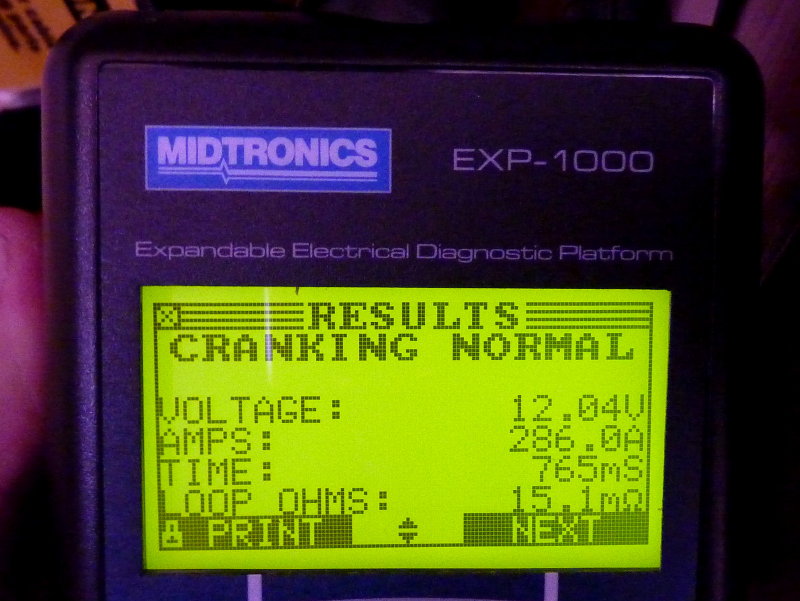
The screen shot above summarizes the averages. Despite a 640A+ peak in-rush the averaged cranking current, from loaded to unloaded starter motor, was just 286A and the total cranking duration was just 0.765 seconds or 765 mS. For what it is worth, this particular bank is protected by a 300A fuse and has done well in excess of 1200 starts, over a 12 year period, and never once nuisance tripped the fuse. Why? Because the duration of a starting event is very short, this one 3/4 of a second, and this does not even come close to the trip-delay curve of the fuse.
Engine Cranking Reality:
There is little dire need on most smaller boats, especially ones with small aux diesels (sub 150 HP) or gas engines, to require a *dedicated starting battery.
*Dedicated Starting Battery – A hard wired battery bank used only for starting purposes and nothing else, unless for emergency situations. A dedicated starting battery is connected directly to the starter motor when the start battery switch is on.
A dedicated starting battery is always nice, but it usually means a new switch and wiring reconfiguration to do it correctly. With many battery switches located in DC panels, & these are usually not ABYC compliant, this is often not an easy undertaking. By tweaking the existing 1/2/B, & how you use it, you can make the system more fool proof and easier to use.
A large chunk of our customers boats have started engines, for years, on their house banks, we’ve now seen the math as to why this is so and why this works. We even have commercial fishing boats starting large Cummins, Cat and John Deere engines with 6V Golf Car batteries.
How? To grasp this we need to understand that a house bank is typically much, much larger than a start bank. Because of this, and even when the batteries are deep-cycle, the house bank almost always has more cranking capacity than the single, & typically small, starting battery. When we parallel batteries, in a house bank, we the cranking capacity is additive. For example, three 100Ah 600 CCA deep-cycle batteries quickly become 1800CCA when wired in parallel.
For owners that understand how to use a 1/2/B, in a more simple manner, this means they only use position #1 (HOUSE) and OFF. The only time to do anything different is when there is an emergency or to occasionally test the reserve-bank to ensure it is still performing well. The 1/2/B works really well as a USE SWITCH, but it can be tweaked to be better.
“But RC the guy down the dock says deep-cycle batteries cannot be used for cranking.”
Sadly, your dock-expert is misleading you on this. I will let Trojan Battery sum this one up.
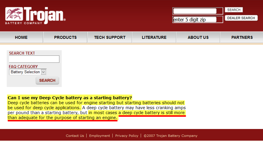
The key here is “a deep-cycle battery“, meaning single battery, and when most all house banks on boats over 25 feet these days are using multiple deep-cycle batteries you now have many more cranking amps in the house bank than you do in your typical starting battery. Even at 50% DoD a typical house bank will still have more cranking capability than a single starting battery. Unless you have massive diesel engines, or a very small single battery house bank, keep it simple and just crank off the house bank. You can now delegate bank #2 as a reserve/emergency bank.
Cascading HEF : “I Forgot to Switch From BOTH Back to HOUSE“
The use of BOTH to start you motor, or when charge directing, requires that you remember move the switch off of the BOTH position when you shut the motor off, or shortly after. Unless you need to be in BOTH for charge directing, there should be no other need for this position, in a well operating system, that’s also properly wired. As discussed above, unnecessary switching can lead to potentially blown alternator diodes, damaged electronics or two dead banks as opposed to just one. Using the BOTH position to start the motor is indeed unnecessary switching that can lead to human error issues.
An expensive scenario is that happens all too often, is when an owner has forgotten to switch off of BOTH and killed both banks. Doing this leaves no second / reserve battery to start the motor with. You’d be surprised how many calls we get each year for this exact issue.
Don’t Blame the Switch:
The normal human tendency, when these blunders or HEF happens, is to blame the “stupid” 1/2/B switch. The 1/2/B switch is like a gun, the gun did not pull the trigger, the owner of the gun did. How is the switch “stupid”? It’s not, but the owner may be. How is the switch “stupid” when the owner makes a mistake? It’s not, it did exactly as it was set & wired to do, but the 1/2/B is still often blamed for owner ineptitude.. This is the bad rap we referenced earlier.
Let’s Make the 1/2/B Easier & More Fool Proof
The 1/2/B as a USE SWITCH:
Converting a 1/2/B to a USE SWITCH is actually quite easy and minimally cost invasive. Once you do this it becomes a SIMPLE ON/OFF scenario. That’s it, ON & OFF, or more accurately #1 & OFF. Once converted to a use switch it is no longer a charge directing switch, or a start on BOTH or #2 then remember to move to #1 switch. It is basically an ON/OFF switch.. Simple, effective and you likely already have one if you’re reading this.
Wiring Upgrades:
The 1/2/B switch is a very useful device and there are a few small changes you can do that can make it even more fool proof. Most of what you need for a very simple and redundant system is already there, so there is little need to spend more money on new switches or drill yet more holes in your boat over what you likely already have. This is of course predicated on the fact that you are comfortable with the idea of not using a dedicated starting battery.
Below Are Illustrating 1/2/B Switch Upgrades in Multiple Levels:
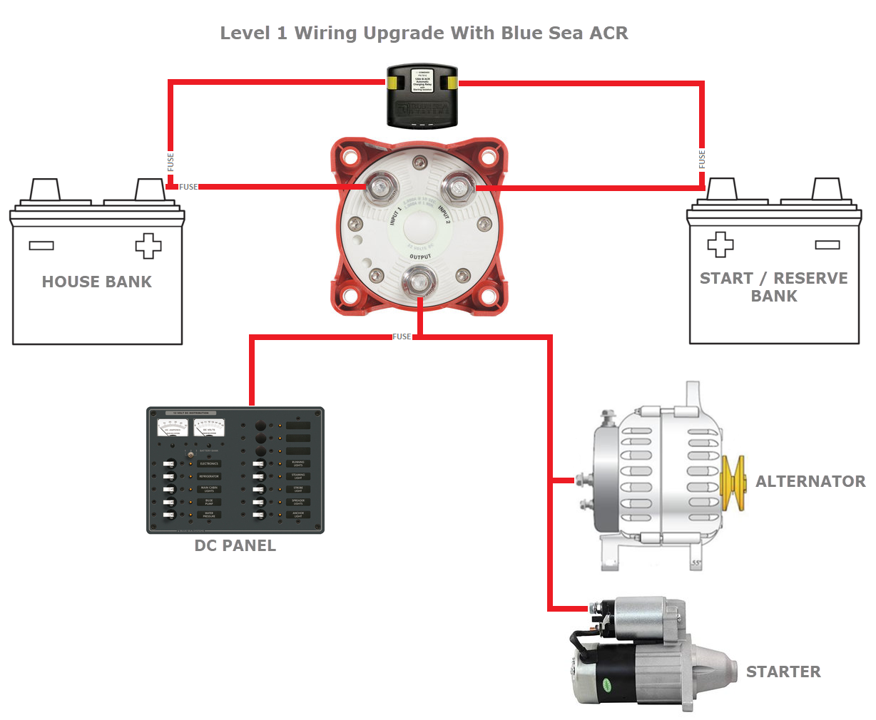
Level 1 Upgrade: In the image below we have the Level 1 Use Switch Upgrade. It consists of adding a Charge Management Device, in the case of this article we have chosen to illustrate the Blue Sea Systems ACR. Once installed the ACR will provide for fully automated charging of both banks. The addition of the ACR eliminates the need to move the switch for charge directing. We’ve also added some fuses, which are required under ABYC standards. Please read our article on Automatic Combining Relays for a better idea of how they work.
You don’t have to use an ACR and the class of “Charge Management Devices is now quite vast. You could also use an:
- Balmar Digital Duo Charger
- Xantrex Echo Charger
- Sterling Power ProBatt Ultra DC to DC Charger
- Victron Orion TR Smart DC to DC Charger
The ACR just represents an excellent low cost option.
Making Sense of Automatic Charging Relays (LINK)
Any bank that can be called upon to start a motor, and with a 1/2/B that is either bank, should ideally have a fuse capable of doing so without nuisance tripping. The bare minimum fuse size, for small diesels, would be 250A but preferably 300A as the minimum. The start bank can also be fused on smaller diesels, but it’s not technically a requirement, under the ABYC standards, to fuse the cranking circuit.
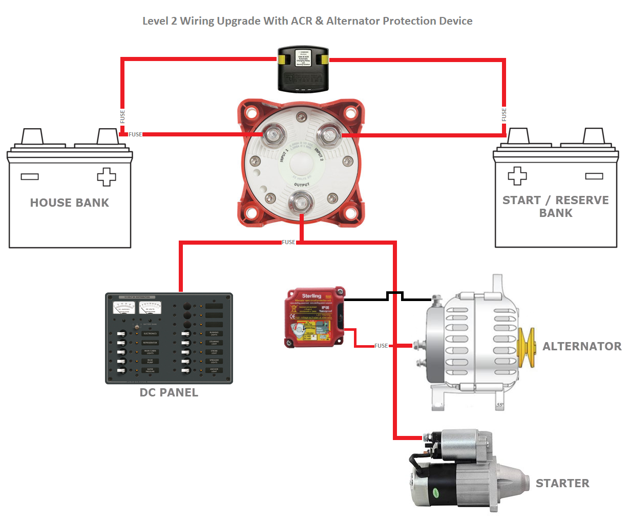
Level 2 Upgrade: In level 1 we reduced the need for unnecessary switching for charge direction by adding a Blue Sea ACR. Unfortunately level 1 leaves open the possibility of a load-dump. The Level 2 upgrade adds a Sterling Power Alternator Protection device to protect against a 1/2/B induced load dump. The alternator is still wired in the factory configuration and we only add an ACR and Alternator Protection Device. You can now get on the boat set the switch to Bank #1 and use the boat. When you’re done flip the switch to OFF. No need for unnecessary switching and human error induced blunders are drastically reduced..
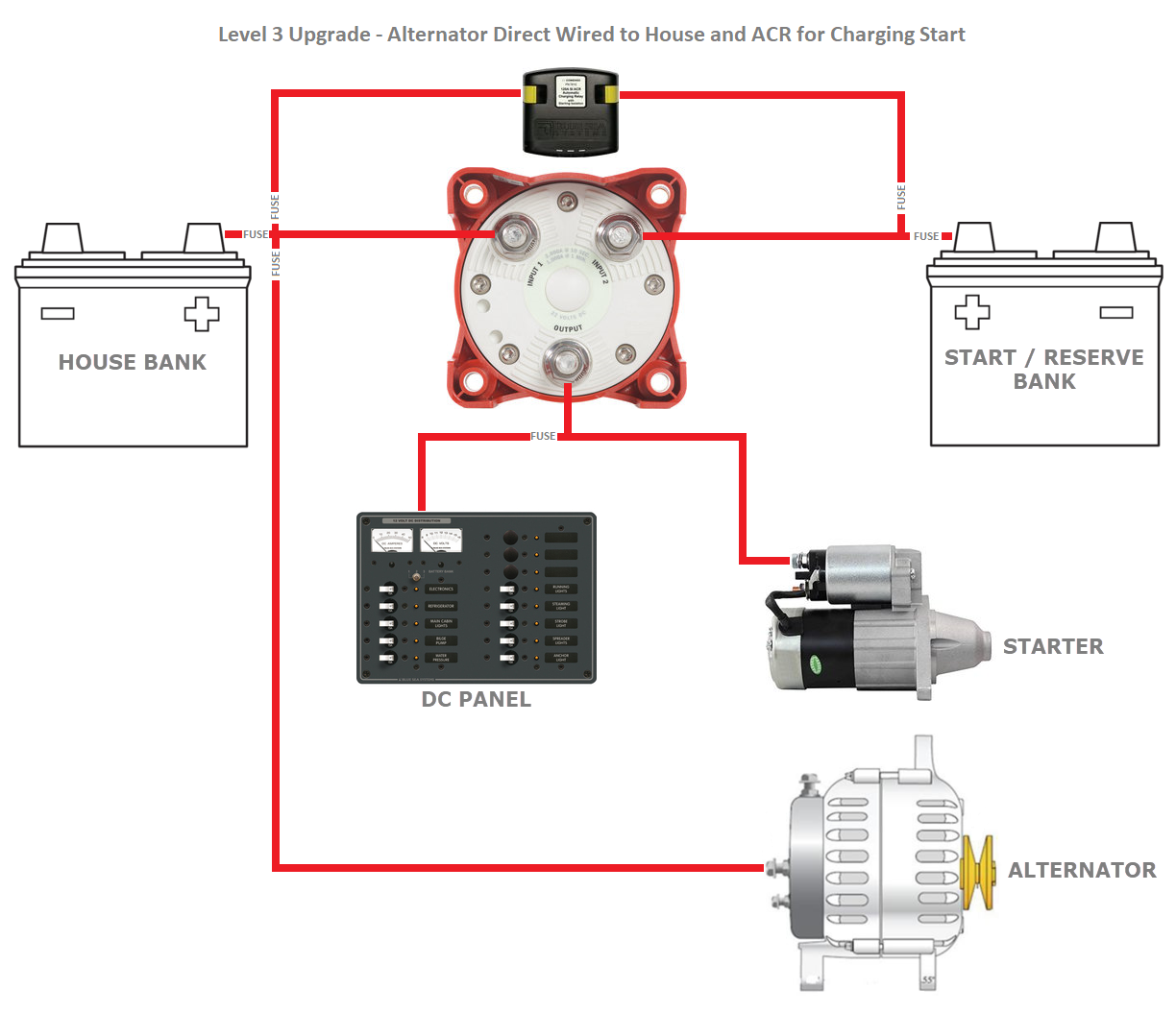
Level 3 Upgrade: The level 3 upgrade wires the alternator directly to the house bank with proper fusing rated at 150% of the alternators rated output and within 7″ of the house banks positive terminal. This upgrade offers optimal charging performance when an owner has an alternator with an external regulator. Wiring direct to the house bank means the alternator cannot be “load-dumped’ by the switch because the alternator is now directly connected to the “load” or bank. The charging performance aspect is realized by the voltage regulator now sensing voltage closer to the bank and this improves fast charging performance. With a 1/2/B in factory wiring configuration the closest you can sense voltage for the alternator is the c-post of the switch. This typically means less than stellar charging performance. For more on this please read:
Alternators & Voltage Sensing – Why It Matters
There are numerous performance benefits for alternator charging when direct wiring the alternator to the house bank. These benefits are above and beyond the elimination of a 1/2/B switch load-dump. There are however some important nuances to the Level 3 upgrade. If you look closely you’ll notice that we’ve moved the ACR connections & alternator input to the load side of the house and start bank fuses.
The reason for this is rather simple. In the event of a bank failure, and we see them, you will want to be able to keep the alternators charging output with the good bank. This can be done simply and easily by removing the house or start bank fuse. The removal of the fuse allows you to 100% isolate the bad bank yet keep alternator charging with the now “reserve” bank.
In the event of a house bank failure you would simply pull the fuse on the house bank and set the 1/2/B to BOTH. The alternator can now charge the start/reserve battery, and the entire vessel can run off that bank while the failure of the house bank is dealt with. An even better approach, than pulling fuses, would be to place an ON/OFF battery switch right after the house bank fuse inside the battery compartment.
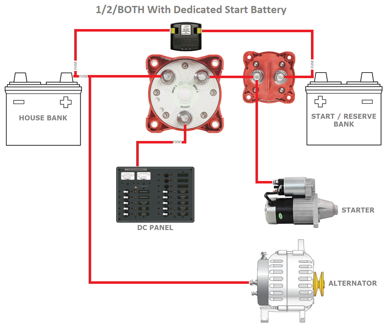
What if I want to keep my 1/2/BOTH and have a dedicated start battery?
Actually this is pretty easy. In the diagram below we’ve taken the Level 3 upgrade and simply added a Blue Sea Systems ON/OFF battery switch. This design means you retain the ability to start off the house bank in an emergency as well as maintain all the safety and isolation features the 1/2/BOTH can offer.
The diagram below is one that works well when an owner desires a dedicated starting battery but also want to retain the flexibility & isolation of the 1/2/BOTH switch.
Simply flip to #1 and ON and your ready to go. When you’re done flip both switches to OFF. Label them carefully, Blue Sea Systems sells the perfect labels.
Use Modes:
For customers with this set up I simply leave a copy of all the scenarios of switch use on-board. This is what it looks like..
NORMAL EVERYDAY USE:
ISOLATED START & HOUSE
Note: Alternator charges HOUSE and ACR charges START.
1/2/BOTH = #1
ON/OFF = ON
EMERGENCY SCENARIOS:
START & HOUSE PARALLEL
Note: This overrides the charge management device & allows more current to charge the START bank.
1/2/BOTH = ALL
ON/OFF = ON
Emergency Situ #1 – START – Provides HOUSE & START Duties:
Note: Use if the HOUSE bank were to fail. This 100% isolates the HOUSE bank & uses the START bank for everything.
ON/OFF = ON
1/2/BOTH = ALL
Remove House Bank Fuse
Emergency Situ #2 – HOUSE – Provides HOUSE & START Duties:
Note: Use if the START bank were to fail. This isolates the START bank & uses the HOUSE bank for everything.
ON/OFF = OFF
1/2/BOTH = ALL
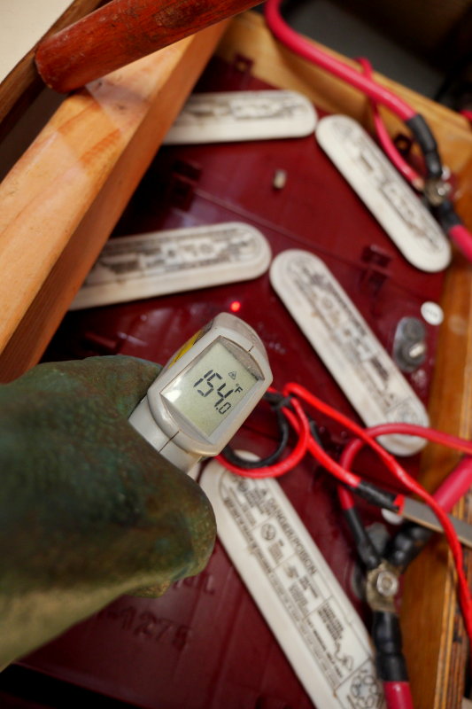
The 1/2/BOTH with an additional ON/OFF is certainly more complicated but more flexible than some other systems. Some battery switches such as the Blue Sea System Dual Circuit Plus force you to use the “combine” feature in an emergency, where you may be paralleling a perfectly good battery bank with one that has an internal short.
Combine as your only emergency option is absolutely not the same as the ability to 100% isolate a bad bank. This image is why you don’t want to combine a good battery to one that has failed or shorted internally. The runaway battery had already been identified and disconnected from the rest of the bank and yet it was still registering 154F.
You Have Lot’s of Options
Before you throw your hands in the air, and potentially throw out a perfectly good battery switch, consider making your 1/2/B switch a USE SWITCH. The 1/2/B as a use switch is still not our favorite switching configuration, but it is often the least expensive upgrade. The upgrades listed above are inexpensive, easy, eliminate needless switching and make the system easier to use.
The options for battery switching are almost limitless, but please always design for:
1- The ability to completely isolate a bank (paralleling with a potentially failed bank is not a suitable option)
2- The ability to use the vessels second bank, for everything, in an emergency
3- Keep it simple & easy to understand.
Good luck and happy boating!
PLEASE HELP!
This site is 100% reader supported. My wife is urging me to shut it down as it just keeps costing us money. My stroke recovery is very costly as is authoring this site and keeping it secure.
Click the DONATE button below if you would like to make a donation via BUY ME A COFFEE.
